ASME B16.9 is the American Society of Mechanical Engineers’ standard titled “Factory-Made Wrought Buttwelding Fittings.” It specifies dimensions, tolerances, testing, and marking requirements for wrought butt-welding fittings used in piping systems,In this article ,you would find all the histories of ASME B16.9 and its latest editions ASME B16.9 2024.
Historical Editions of ASME B16.9
The evolution of ASME B16.9 reflects the industry’s advancements and the need for standardized piping components:
- 1940: Initial publication as ASA B16.9-1940 by the American Standards Association (ASA).
- 1951 & 1958: Revisions expanded size ranges and fitting types.
- 1964: Further revisions to clarify standards and include more fitting types.
- 1971: Published as ANSI B16.9-1971 under the American National Standards Institute (ANSI).
- 1978: Major revision introducing decimal dimensions and metric equivalents.
- 1986: Transitioned to ASME/ANSI B16.9-1986, establishing inch dimensions as standard.
- 1993: Included dimensions for short pattern lap joints.
- 2001: Added short radius elbows and returns, incorporating ASME B16.28-1994.
- 2003: Permitted fabricated lap joint stub ends with specific welding methods.
- 2007: Introduced segmental elbow requirements and 3D elbow dimensions.
- 2012: Revised design proof test procedures and updated references.
- 2018: Merged U.S. customary and metric tables, updated design proof test requirements, and clarified design methods.
- 2024: Latest edition with significant updates
Latest Edition: ASME B16.9-2024
The ASME B16.9-2024 edition, published on October 16, 2024, introduces several key updates compare with ASME B16.9 2018
You can download ASME B16.9-2024 standard pdf freely here
Changes from ASME B16.9-2018 to ASME B16.9-2024
1. Enhanced Design Proof Testing Requirements
- Minimum Design Thickness: The 2024 edition mandates defining minimum requirements for determining design thickness in critical areas of fittings.
- Sample Pressure Test Reports: Inclusion of sample reports to standardize documentation and ensure consistency across manufacturers.
- Retesting Criteria: Clarifies conditions under which retesting is necessary, especially when significant changes in geometry or manufacturing methods occur
2. Updated Tables and Appendices
- Table Revisions: Tables 6.1-10 and 11.2-1 have been updated to reflect current industry practices and material specifications.
- Nonmandatory Appendix B: Revised to provide additional guidance on design considerations and testing procedures.
3. Marking and Traceability Enhancements
- Nominal Wall Thickness Marking: Introduces options for marking nominal wall thickness on fittings, improving traceability and compliance verification.
- Proof Test Report Requirements: Now require detailed information, including material grade, material group, and manufacturing method, to ensure transparency and accountability.
4. Clarifications on Previous Editions
- The 2024 standard provides guidance on the acceptability of fittings manufactured under previous editions, emphasizing the importance of documented design conformity and criteria for type testing.
ASME B16.9 2024
ASME B16.9 2024 specified the fitting type,size,wall thickness tolerance etc
- Fitting Types: Elbows, tees, reducers, caps, and crosses.
- Size Range: NPS ½ through NPS 48 (DN 15 through DN 1200).
- Wall Thickness: Applicable to fittings of any producible wall thickness.
- Tolerance of ASME B16.9
Standard marking specified in ASME B16.9
Each pipe fitting marks permanently , indicating the following content:
The name or trademark of the manufacturer
Material identification mark (ASTM or ASME level symbol)
Wall thickness serial number or nominal wall thickness
Specifications – Engineering pipe diameter (NPS) related to end connection should be used
Compliance – standard and special pipe fittings
Fittings Material for ASME B16.9
Wrought fittings covered by this Standard shall be in accordance with ASTM A234, ASTM A403, ASTM A420, ASTM A815, ASTM B361, ASTM B363, ASTM B366, or the corresponding specification listed in ASME BPVC, Section II. The term “wrought” denotes fittings made of pipe, tubing, plate, or forgings. For purposes of determining proof testing requirements of section 9, the materials are grouped by similar properties as shown in below table
| Group No. | Material | Standards |
|---|---|---|
| 1 | Carbon and low – alloy steels | ASTM A234/A234M and ASTM A420/A420M |
| 2 | Austenitic and duplex stainless steels | ASTM A403/A403M and ASTM A815/A815M |
| 3 | Nickel alloys | ASTM B366/B366M |
| 4 | Aluminum alloys | ASTM B361 |
| 5 | Titanium alloys | ASTM B363 |
Carbon Steel: ASTM A234 WPB, WPC
Alloy Steel: ASTM A234 WP5, WP9,WP11, WP22,WP91,WP92
Stainless Steel: ASTM A403 WP304, WP304L, WP316, WP316L, WP321, WP347
Nickel Alloys: Inconel, Monel, Hastelloy
Duplex & Super Duplex Stainless Steel
ASME B16.9 FITTING DIMENSIONS
General size range for. B16.9 fittings
NPS ½” to 48″ (DN 15 to DN 1200)
Dimensions apply to seamless and welded fittings
Covers standard wall thicknesses (Sch 10 to Sch 160, XS, XXS)
Fitting Types
Fitting Types: Elbows, tees, reducers, caps, and crosses.
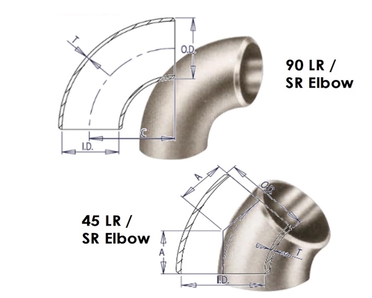
1. ASME B16.9 Elbows (90° & 45°& 180°) & Special degree elbows available
| Type | Radius |
| 90° Long Radius (LR) | 1.5 × NPS |
| 90° Short Radius (SR) | 1.0 × NPS |
| 45° Elbow | – |
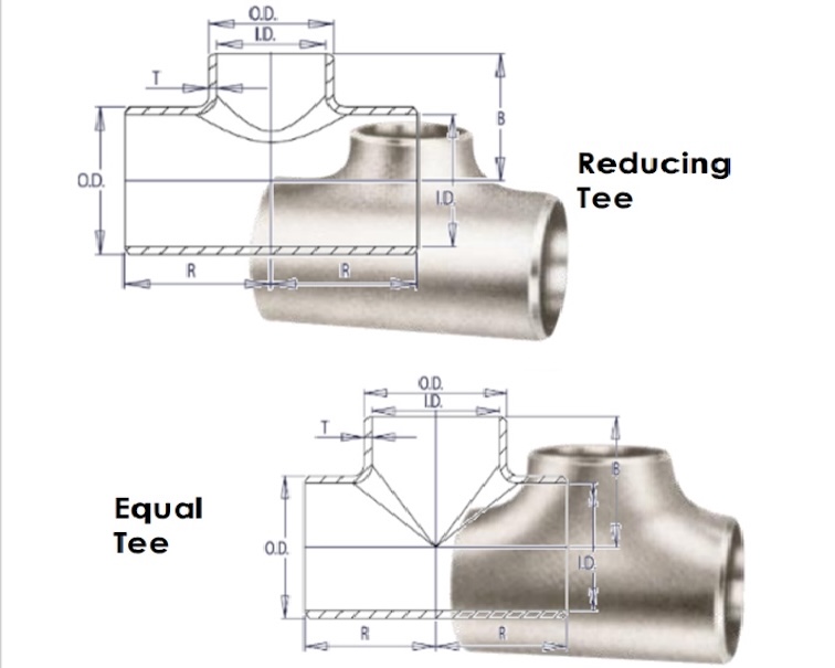
2,ASME B16.9 Butt Weld Equal Tee Reducing Tee
| Type | Description |
| Straight Tee | Equal branch sizes |
| Reducing Tee | Smaller branch size |
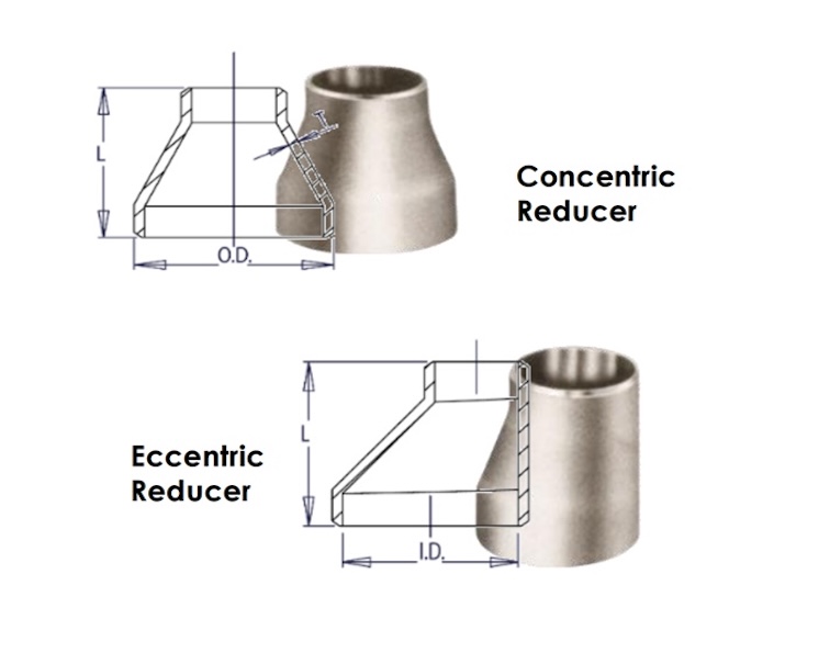
3. ASME B16.9 Reducers
| Type | Description |
| Concentric Reducer | Centerline remains aligned |
| Eccentric Reducer | Offset centerlines |
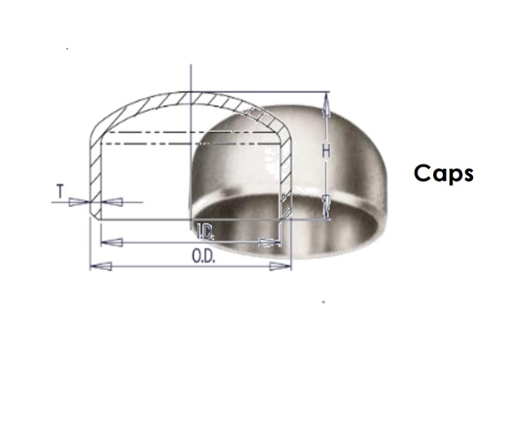
4. ASME B16.9 Caps
| Type | Description |
| Cap | Closes pipe ends |
- Ends a pipe run
5. Crosses
| Type | Description |
| Equal Cross | Four-way connection |
| Reducing Cross | One branch smaller |
ASME B16.9 FITTING DIMENSIONS tables
ASME B16.9-2024 Elbow Dimension
ASME B16.9-2024 Buttwelding Reducer Dimension
ASME B16.9-2024 Buttwelding Cap Dimension
ASME B16.9-2024 Buttwelding Stub End Dimension
ASME B16.9 FITTING DIMENSIONS Tolerance
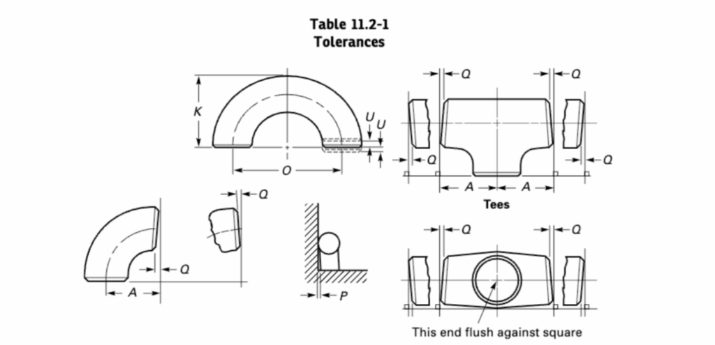
The illustration of dimension tolerances of ASME B16.9 pipe fittings.
1. General Tolerances for All Fittings of ASME B16.9
| NPS | DN | O.D | I.D | Off Angle, Q | Off Plane, P |
|---|---|---|---|---|---|
| 1/2~2-1/2 | 15~65 | +1.6, -0.8 | ±0.8 | ±1 | ±2 |
| 3~3-1/2 | 80~90 | ±1.6 | ±1.6 | ±2 | ±4 |
| 4 | 100 | ±1.6 | ±1.6 | ±3 | ±5 |
| 5~8 | 125~200 | +2.4, -1.6 | ±1.6 | ±3 | ±6 |
| 10~18 | 250~450 | +4.0, -3.2 | ±3.2 | ±4 | ±10 |
| 20~24 | 500~600 | +6.4, -4.8 | ±4.8 | ±5 | ±10 |
| 26~30 | 650~750 | +6.4, -4.8 | ±4.8 | ±5 | ±13 |
| 32~48 | 800~1200 | +6.4, -4.8 | ±4.8 | ±5 | ±19 |
*All dimensions are in mm unit. NPS: Nominal Pipe Size; DN: Nominal Diameter.
*O.D: outside diameter at bevel; I.D: inside diameter at end; Both P & Q are angularity tolerances.
*A minimum wall thickness of 87.5% should apply unless otherwise specified by the purchaser.
2. Tolerances of Center-to-End & Overall Length Dimensions
| NPS | DN | *I | *II | *III | *IV |
|---|---|---|---|---|---|
| 1/2~2-1/2 | 15~65 | ±2 | ±3 | ±2 | ±3 |
| 3~3-1/2 | 80~90 | ±2 | ±3 | ±2 | ±3 |
| 4 | 100 | ±2 | ±3 | ±2 | ±3 |
| 5~8 | 125~200 | ±2 | ±3 | ±2 | ±6 |
| 10~18 | 250~450 | ±2 | ±3 | ±2 | ±6 |
| 20~24 | 500~600 | ±2 | ±3 | ±2 | ±6 |
| 26~30 | 650~750 | ±3 | ±6 | ±5 | ±10 |
| 32~48 | 800~1200 | ±5 | ±6 | ±5 | ±10 |
*All dimensions are in mm unit.
*I refers to the tolerances for center-to-end dimensions of 90° & 45° long and short radius elbows and tees, A, B, C, M.
*II refers to the tolerances for center-to-end dimensions of 3D radius elbows, A, B.
*III refers to the tolerances for overall length of reducers and lap joint stub ends, F, H.
*IV refers to the tolerances for overall length of caps, E.
3. Tolerances for 180° Returns & Lap Joint Stub Ends
| NPS | DN | 180° Return | Lap Joint Stub Ends | ||||
|---|---|---|---|---|---|---|---|
| inch | mm | O | K | U | G | R | T |
| 1/2~2-1/2 | 15~65 | ±6 | ±6 | ±1 | +0, -1 | +0, -1 | +1.6, -0 |
| 3~3-1/2 | 80~90 | ±6 | ±6 | ±1 | +0, -1 | +0, -1 | +1.6, -0 |
| 4 | 100 | ±6 | ±6 | ±1 | +0, -1 | +0, -2 | +1.6, -0 |
| 5~8 | 125~200 | ±6 | ±6 | ±1 | +0, -1 | +0, -2 | +1.6, -0 |
| 10~18 | 250~450 | ±10 | ±6 | ±2 | +0, -2 | +0, -2 | +3.2, -0 |
| 20~24 | 500~600 | ±10 | ±6 | ±2 | +0, -2 | +0, -2 | +3.2, -0 |
*All dimensions are in mm unit.
*O:center-to-center dimensions; K:back-to-face dimensions; U:alignment of ends.
*G:outside diameter of lap; R:fillet radius of lap; T:Lap thickness.