We are a leading manufacturer and global supplier of MSS SP-44 Steel Pipeline Flanges, offering a full range of weld neck and blind flanges for high-pressure pipeline applications. Our flanges are engineered to meet the most demanding requirements of oil, gas, petrochemical, and offshore industries.
SCOPE
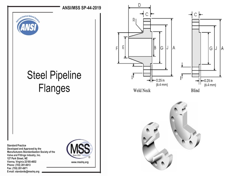
1.1 General This Standard Practice covers pressure-temperature ratings, materials, dimensions, tolerances, marking, and testing for steel pipeline flanges. The welding neck type flanges shall be forged steel, and the blind flanges may be made from either forged steel or from steel plate.
1.1.1 Dimensional and tolerance requirements for NPS 10 and smaller are provided by reference to ASME B16.5. When such flanges are produced from materials meeting Table 2 requirements, and meet all other stipulations of this Standard Practice, then they shall be considered as complying therewith.
1.1.2 This Standard Practice covers two Product Specification Levels (PSL). If no PSL is specified, material shall be supplied as PSL1 with the standard requirements as are contained in the body of this Standard Practice. If PSL2 is specified, the material shall meet the additional requirements specified in Supplementary Requirement SR – 18 (see Annex D/D.1).
Pressure Temperature Ratings
Flanges understand the standard has follwing pressure ratings: Class 150, 300, 400, 600 or 900.
Sizes
NPS and DN as follows:
| NPS | 12 | 14 | 16 | 18 | 20 | 22 | 24 | 26 | 28 | 30 | 32 | 34 | 36 |
| DN | 300 | 350 | 400 | 450 | 500 | 550 | 600 | 650 | 700 | 750 | 800 | 850 | 900 |
| NPS | 38 | 40 | 42 | 44 | 46 | 48 | 50 | 52 | 54 | 56 | 58 | 60 | |
| DN | 950 | 1000 | 1050 | 1100 | 1150 | 1200 | 1250 | 1300 | 1350 | 1400 | 1450 | 1500 | |
Materials for MSS SP 44 Flanges
3.1 The steel used in the manufacture of these flanges shall be selected by the manufacturer to meet the following requirements.
3.1.1 All materials used for flanges shall be fully killed steel made to fine grain practice as defined in ASTM A941. Welding neck flanges shall be made from forgings. Blind flanges may be made from either forged steel or from steel plate.
The selected material shall meet the specified chemistry limits in Table 1, grade requirements of Table 2, and other provisions of Section 3.
A ladle and product analysis shall be performed in accordance with ASTM A961/A961M and the results shall be reported on the Certified Material Test Report (CMTR). The product analysis is subject to over/under tolerances as specified in ASTM A961/A961M.
3.1.2 The steel used shall be suitable for field welding to other flanges, fittings, or pipe manufactured according to ASTM A105/A105M, ASTM A53/A537M, ASTM A106/A106M, ASTM A350/A350M, ASTM A381, ASTM A516/A516M, ASTM A537/A537M, ASTM A694/A694M, ASTM A707/A707M, or API Specification 5L
Chemical Composition of MSS SP44 Flange
Table 1
| Element | Limits (%) | |
|---|---|---|
| Min. | Max. | |
| C | – | 0.30 |
| Mn | 0.60 | 1.60 |
| P | – | 0.025 |
| S | – | 0.025 |
| Si | 0.15 | 0.35 |
| Cu | – | 0.40 |
| Ni | – | 0.40 |
| Cr | – | 0.30 |
| Mo | – | 0.12 |
| V | – | 0.11 |
| Nb | – | 0.05 |
| B | – | 0.001 |
| Cu+Ni+Cr+Mo | – | 1.00 |
Tensile Requirements of MSS SP44 flange material
SI (Metric) and U.S. Customary
Table 2.
| Grade | Yield Point (Min.) | Tensile Strength (Min.) | Elongation 50mm (2 in.) (Min. %) | |||
|---|---|---|---|---|---|---|
| Mpa | ksi | Mpa | ksi | |||
| F36 | 248 | 36 | 414 | 60 | 20 | |
| F42 | 290 | 42 | 414 | 60 | 20 | |
| F46 | 317 | 46 | 414 | 60 | 20 | |
| F48 | 331 | 48 | 427 | 62 | 20 | |
| F50 | 345 | 50 | 441 | 64 | 20 | |
| F52 | 359 | 52 | 455 | 66 | 20 | |
| F56 | 386 | 56 | 469 | 68 | 20 | |
| F60 | 414 | 60 | 517 | 75 | 20 | |
| F65 | 448 | 65 | 531 | 77 | 18 | |
| F70 | 483 | 70 | 552 | 80 | 18 | |
| F80 | 550 | 80 | 620 | 90 | 16 | |
Hardness of MSS Sp 44 Flange
Two hardness tests shall be made for each heat treatment lot by the Brinell method as specified in ASTM A370. When more than one forging is produced from each heat, a minimum of two forgings shall be tested with one reading from each forging. When only one forging is produced, it shall be tested in two locations. Hardness shall be HBW 235 as a maximum.
3.1.7 Repair by Welding
Repair by welding is only permitted by agreement with purchaser. Weld repair procedure and welder qualifications shall be per ASME BPVC, Section IX.
3.2 Bolting
The bolting listed in Table 3 shall be used in flanged joints covered by this Standard Practice. Bolting produced from other materials may be used if permitted by the applicable code or governmental regulation. All bolting materials are subject to the following limitations.
3.2.1 High Strength Bolting Bolting materials having allowable stresses not less than those for ASTM A193/A193M, Grade B7 are listed as high strength in Table 3. These and other materials of comparable strength may be used in any flanged joint.
3.2.2 Intermediate Strength Bolting The bolting materials listed as intermediate strength in Table 3, and other bolting of comparable strength, may be used in any flanged joint, provided the user verifies their ability to seat the selected gasket and maintain a sealed joint under expected operating conditions.
Low Strength Bolting
3.2.3 Low Strength Bolting Bolting materials having not more than 207 MPa (30 ksi) specified minimum yield strength are listed as low strength in Table 3. These materials and others of comparable strength shall be used only in Class 150 and Class 300 joints, and only with gaskets as described in Section 3.3.2.
List of Bolting Specifications
| ASTM BOLTING MATERIALS | ||||||
|---|---|---|---|---|---|---|
| HIGH STRENGTH(a) | INTERMEDIATE STRENGTH(b) | LOW STRENGTH(c) | ||||
| SPEC.—GRADE | NOTES | SPEC.—GRADE | NOTES | SPEC.—GRADE | NOTES | |
| A193/A193M-B7 | — | A193/A193M-B5 | — | A193/A193M-B8 CL1 | (g) | |
| A193/A193M-B16 | — | A193/A193M-B6 | — | A193/A193M-B8C CL1 | (g) | |
| A320/A320M-L7 | (d) | A193/A193M-B6X | — | A193/A193M-B8M CL1 | (g) | |
| A320/A320M-L7A | (d) | A193/A193M-B7M | — | A193/A193M-B8T CL1 | (g) | |
| A320/A320M-L7B | (d) | A193/A193M-B8 CL2 | (f) | A193/A193M-B8A | — | (g) |
| A320/A320M-L7C | (d) | A193/A193M-B8 CL2B | (f) | A193/A193M-B8CA | — | (g) |
| A320/A320M-L43 | (d) | A193/A193M-B8C CL2 | (f) | A193/A193M-B8MA | — | (g) |
| A354-BC | — | A193/A193M-B8M CL2 | (f) | A193/A193M-B8TA | — | (g) |
| A354-BD | — | A193/A193M-B8M CL2B | (f) | A307-B | — | (h) |
| A540/A540M-B21 | — | A193/A193M-B8T CL2 | (f) | A320/A320M-B8 CL1 | (g) | |
| A540/A540M-B22 | — | A320/A320M-B8 CL2 | (f) | A320/A320M-B8C CL1 | (g) | |
| A540/A540M-B23 | — | A320/A320M-B8C CL2 | (f) | A320/A320M-B8M CL1 | (g) | |
| A540/A540M-B24 | — | A320/A320M-B8F CL2 | (f) | A320/A320M-B8T CL1 | (g) | |
| A320/A320M-B8M CL2 | (f) | |||||
| A320/A320M-B8T CL2 | (f) | |||||
| A449 | — | (i) | ||||
| A453/A453M-651 | — | (e) | ||||
| A453/A453M-660 | — | (e) |
HEAT TREATMENT of MSS SP 44 Flange
The F42 and higher grades of all pressure classes shall be normalized, normalized and tempered, quenched and tempered, or precipitation treated and aged as defined in ASTM A961/A961M; and the Class 400 and higher classes of Grade F36 flanges shall be annealed, normalized, normalized and tempered, or quenched and tempered as defined in ASTM A961/A961M; however, the minimum tempering temperature shall be 540 °C (1000 °F).
4.2 It is recognized that the cooling rate in a quenching operation may be slower in the thicker ring section of the flange than in the thinner hub section. Hence, the increase in yield strength due to the quenching operation may be less in the ring section than in the hub section. This factor is accounted for in Section 5.3 on design. The NPS 38 and larger sizes of the Class 300 and higher classes of welding neck flanges shall have 290 MPa (42 ksi) minimum yield strength in the ring section.
FLANGE DESIGN of MSS SP 44
5.1 Drilling Templates Drilling templates are derived as follows:
5.1.1 Class 150 flange drilling templates are the same as ASME B16.5 and Class 125 of ASME B16.1.
5.1.2 The NPS 24 and smaller Class 300 flanges have drilling templates which are the same as ASME B16.5 and Class 250 of ASME B16.1. NPS 24 and smaller Class 400, 600, and 900 drilling templates are the same as ASME B16.5.
5.1.3 The NPS 26 through NPS 60 Classes 150, 300, 400, 600, and 900 flanges have drilling templates, which are the same as ASME B16.47, Series A flanges.
5.2 Flange Ring Design
The outside diameter and flange thickness of NPS 24 and smaller flanges are in accordance with ASME B16.5. The outside diameter and flange thickness of NPS 26 through NPS 60 flanges are in accordance with ASME B16.47, Series A flanges. Larger sizes NPS 26 through NPS 60 were designed in accordance with ASME BPVC, Section VIII, Division 1, Appendix 2, and the flange ring shall have sufficient pressure capacity for the service based on its strength in the normalized condition. This capacity shall be substantiated by ASME BPVC, Section VIII, Division 1, Appendix 2, “Rules for Bolted Flange Connections with Ring Type Gaskets”; with allowable design stresses as given in Annex A of this MSS Standard Practice.
5.3 Hub Design
It should be recognized that ASME B16.5 and ASME B16.47 base their welding neck flange ratings on their hubs at the welding ends having a thickness at least equal to that calculated for pipe having a 276 MPa (40 ksi) specified minimum yield strength and a maximum bore size. It should be recognized that when matching thinner wall, high strength pipe that existing hub designs in ASME B16.5 and ASME B16.47 may not be adequate unless the following requirements are met:
5.3.1 NPS 60 and Smaller When the mechanical (minimum yield strength) properties of all sections of the flanges are equal to or higher than those of the pipe to be matched, the hub dimensions may be the same as those of ASME B16.5 or ASME B16.47, Series A.
5.3.2 In addition, when the minimum yield strength of the hub portion of any flange or its representative test specimen is less than specified for the pipe to be matched, the minimum thickness of the hub at the welding end shall be such that the product of its thickness times its yield strength (at welding end) shall at least equal the product of the specified nominal wall thickness and minimum specified yield strength of the pipe to be matched. Under these conditions, NPS 24 and smaller flanges may also have a single taper hub and the outside diameter of the hub at the base may be modified in accordance with ASME BPVC, Section VIII, Division 1, Appendix 2 calculations.
5.3.3 When the manufacturer employs this option, the flange identification should be a combination of the class of material of the flange and of the pipe for which the flange has been designed. See Section 6.1.
5.3.4 When the hub thickness at the welding end must be greater than the adjoining pipe, the joint design shall be as shown in any of the three sketches in Figure 1.
5.3.5 Dual Slope Hubs For NPS 24 and smaller, dual slope (also known as “ANSI” or “tangent”) hubs as defined in ASME B16.5 are acceptable in all instances. If substituting wall thickness for yield strength per Section 5.3.2, one must increase the outside diameter of the entire welding end tangent section accordingly. For material larger than NPS 24, dual slope hubs may only be employed when the minimum yield strength of the flange is the same or higher than the mating pipe. If substituting wall for yield per Section 5.3.2 on these larger sizes, one must use the single slope (also known as “pipeline”) hub defined herein.
5.4 Welding End
The welding end shall be in accordance with Figure 2 for wall thickness (of intended mating pipe) of 22 mm (0.88 in.) and less. For thicker walls, refer to Figure 3.
5.5 Blind Flanges
5.5.1 The outside diameter and thickness of blind flanges shall be as listed in Tables 6, 7, 8, 9, 10, C2, C3, C4, C5, and C6. Thicknesses listed are based on material having mechanical properties for Grade F36 of Table 2. Drilling templates are as specified in Section 5.1.
Thinner flanges of higher strength material may be furnished in accordance with Annex B design criteria.
5.5.2 Blind flanges need not be faced in the center if, when this center is raised, its diameter is at least 127 mm (5 in.) smaller than the nominal pipe size. When the center part is depressed, its diameter shall not be greater than the gasket I.D. specified in Tables 5 and C1, less 51 mm (2 in.).
Equation: I.D. – 51 mm (2 in.) = Max. Depression O.D.
5.6 Blind Flanges NPS 10 and Smaller
Dimensional requirements for NPS 10 and smaller blind flanges shall be in accordance with ASME B16.5.
5.7 Flat Face Flanges
This Standard Practice permits flat face flanges in all classes, by providing flanges having either the full thickness or the thickness with the raised face removed, without reduction of the pressure-temperature ratings subject to the following provisions:
5.7.1 The thickness of a Class 150 or 300 flange from which the raised face has been removed shall be no less than the applicable dimension “C” of Tables 6, 7, C2, and C3.
5.7.2 The thickness of a flange of Class 400 or higher from which the raised face has been removed shall be no less than the applicable “C” dimension of Tables 8, 9, 10, C4, C5, and C6.
5.7.3 The flange facing shall conform to Section 7.2 for the full width of seating of the gasket.
MARKING of MSS SP 44 Flange
6.1 Flanges shall be marked in accordance with the rules established in MSS SP-25. In addition, the letters, “PL” shall precede the grade symbol marking. The grade symbol marked on the Welding Neck Flange shall designate the grade of material in the welding end of the hub. When flanges are produced under the option of Section 5.3.2, the marking will also include the grade of the material of the pipe which the flange will match.
Example: A flange having a Grade F42 hub designed to be used with Grade X60 pipe would contain the marking PL F42/X60, in addition to the marking specified in MSS SP-25.
6.2 Flanges that are NPS 10 and smaller produced to ASME B16.5 dimensions, and complying with all other requirements of this Standard Practice, shall be marked in accordance with Section 6.1.
6.3 In addition to the marking specified in MSS SP-25, the Charpy temperature shall be identified using the designation MXC, MXF, PXC, or PXF, with “X” corresponding to the Charpy run temperature.
Example: For a Charpy run at -45 °C, the designation would be M45C, or for a test run at 20 °F, the designation would be P20F.
6.4 If the carbon equivalent is over 0.45%, the actual CE shall be marked.
Example: “CE = 0.46”
6.5 For flanges ordered as PSL2, marking shall include “PSL2” after the grade and the unique traceability code number (Annex D.1, SR-18).
FACINGS of MSS SP 44 Flanges
7.1 Flange Facing Finish The finish of contact faces of pipe flanges shall be judged by visual comparison with Ra Standards (see ASME B46.1) and not by instruments having stylus tracers and electronic amplification. The finishes required are given below. Other finishes may be furnished by agreement between user and manufacturer.
7.2 Raised Face Either a serrated-concentric or serrated-spiral finish having from 3.2 μm (125 μin.) to 6.3 μm (250 μin.) average shall be furnished. The cutting tool employed should have an approximate 1.5 mm (0.06 in.) or larger radius, and there should be from 1.7 to 2.2 grooves per mm (44 to 55 grooves per in.).
7.3 Ring Joint The side wall surface of the gasket groove shall not exceed 1.6 μm (63 μin) roughness.
7.4 Flange Facing Finish Imperfections In the flange facing finish, imperfections shall not exceed the dimensions shown in Table 11. Adjacent imperfections shall be separated by a distance of at least four times the permissible radial projection. Protrusions above the serrations are not allowed.
MSS SP 44 Flange Dimension Tolerance
| Item | Description | Specification | Tolerance |
|---|---|---|---|
| Facing | Ousied Diater of Raised Face | 2.0 mm (0.06 in.) | 12≤NPS≤24: ±1.0 mm (±0.04 in) NPS≥26: ±2.0 mm (±0.08 in) |
| 7.0 mm (0.25 in.) | 12≤NPS≤24: ±0.5 mm (±0.02 in) NPS≥26: ±2.0 mm (±0.04 in) | ||
| Raised Face Height | All NPS | ±1.0 mm (±0.04 in.) | |
| Ring – Joint Facing | L (Depth of Groove) | +0.4 mm, -0.0 mm (+0.016 in., -0.000 in) | |
| D (Width of Groove) | ±0.2 mm (±0.008 in.) | ||
| P (Pitch Diameter) | ±0.13 mm (±0.005 in.) | ||
| r (Groove Fillet Radius) – r ≤ 2mm (0.8 in) | |||
| r (Groove Fillet Radius) – r > 2mm (0.8 in) | |||
| 23°Angel | ±1/2° | ||
| Flange Thickness | NPS ≤ 18 | +3.0 mm, -0.0 mm (+0.12 in., -0.0 in.) | |
| NPS ≥20 | +5.0 mm, -0.0 mm (+0.19 in., -0.0 in.) | ||
| Hub Dimensions | Nominal Outside Diameter of Welding End of Welding Neck Flange | 12≤NPS≤24 | +4.0mm, -1.0 mm (+0.016 in., -0.03 in) |
| NPS≥26 | +5.0mm, -1.5 mm (+0.21 in., -0.06 in) | ||
| Nominal Outside Diameter of Welding End of Welding Neck Flange | 12≤NPS≤18 | ±1.5 mm (±0.06 in) | |
| NPS≥20 | +3.0mm, -1.5 mm (+0.12 in., -0.06 in) | ||
| Overall Length through hub on Welding Neck Flanges | 12≤NPS≤24 | +3.0mm, -5.0 mm (+0.12 in., -0.18 in) | |
| NPS≥26 | ±5.0 mm (±0.19 in) | ||
| Drilling and Facing | Bolt Hole Diameter | +2.5mm, -0.5mm (+0.10 in., -0.02 in) | |
| Bolt Circle Diameter | ±1.5 mm (±0.06 in) | ||
| Center to Center of Adjacent Bolt Holes | ±0.8 mm (±0.03 in) | ||
| Eccentricity between Bolt Circle Diameter and Machined Facing Diameters | 12≤NPS≤24 | 1.5 mm (0.06 in.) | |
| NPS≥26 | 2.0 mm (0.09 in. |
MANUFACTURING AND INSPECTION
11.1 Flanges shall be manufactured in accordance with a documented Manufacturing Procedure Specification (MPS). If specified by the purchaser, manufacturing shall not proceed until the MPS has been accepted by the purchaser.
The MPS shall specify the following items, as applicable:
- Product form (ingot, billet, bar) and dimensions of the starting material;
- Forging method and temperature;
- Heat treatment procedure, including thermal cycles;
- Machining requirements;
- Mechanical test sample origin (starting material or finished product) and locations;
- Dimensions, inspection and test requirements;
- Non-destructive examination (NDE) procedures and results;
- Traceability of finished product back to raw material;
- Other order-specified additional requirements such as special facing, coating, marking, etc.
11.2 Inspection and Test Plan (ITP) The inspection and testing to be performed during qualification and production shall be as summarized in the chart below. When requested, hold points required by the purchaser shall be identified on a submitted and approved ITP.
| Inspection and Test Plan Requirements (from Section 11.2) | ||
|---|---|---|
| Type of Test (Mandatory Requirements) | Section of SP-44 | Number of Tests |
| Chemical Analysis | 3.1.1, SR-6 | Ladle and Product analysis per heat |
| Tensile Test | 3.1.4, SR-2 | 1 per lot |
| Impact Testing (Grades over F42) | 3.1.5, SR-3 | 1 set of 3, or by agreement |
| Hardness Test | 3.1.6, SR-13 | 2 per lot or each flange (SR-13) |
| Visual Inspection | 7.4 | Each flange |
| Dimensional Checks | 10, Tables 6 – 10 (C2 – C6) | Per MPS |
| Type of Test (Optional Requirements) | Section of SP-44 | Number of Tests |
| Impact Testing (Grade F36 and F42) | 3.1.5, SR-3 | 1 set of 3, or by agreement |
| Full Section UT | SR-4 | Each flange or by agreement |
| MT/PT Beveled Ends | SR-7 | Each flange or by agreement |
| Sour Gas Applications | SR-1 | By agreement |
| Simulated Post-Weld Heat Treatment | SR-8 | By agreement |
| PSL2 | SR-18 | Per Annex D.1 |
MSS SP-44 vs ASME B16.5 Flanges
| Item | MSS SP-44 | ASME B16.5 |
|---|---|---|
| Typical Size | 12″ – 60″ | Up to 24″ |
| Application | Pipelines | Process piping |
| Weight | Lighter | Heavier |
| Industry | Oil & gas | General industry |
MSS SP-44 steel pipeline flanges are specifically engineered for large diameter, high-pressure oil and gas transmission pipelines. With optimized dimensions, high-strength materials, and compatibility with API line pipe systems, MSS SP-44 flanges provide reliable and cost-effective performance for critical pipeline applications.