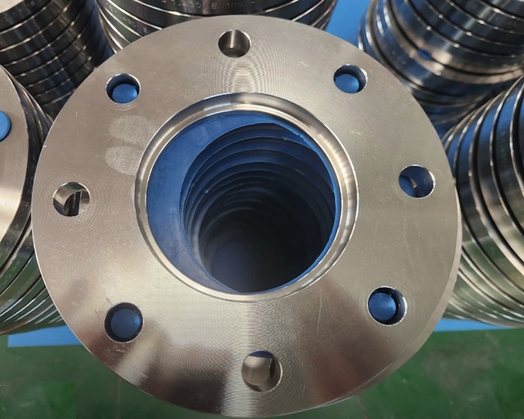
DIN 2544 PN25 Slip On Flange
DIN 2544 Specification
Title: Flat Flanges for Welding (Slip-On) — PN 25
Standard Type: German DIN standard for circular steel slip-on welding flanges.
DIN 2544 covers flat slip-on flanges designed for welding to pipe ends, with a nominal pressure rating of PN 25.
It defines:
- Flange dimensions
- Bolt hole configuration
- Facing types
- Materials
- Tolerances
DIN 2544 Flange Pressure Rating
- PN 25 = Maximum allowable working pressure 25 bar at 20 °C (≈ 362 psi)
- Pressure-temperature ratings vary according to material and follow DIN 2401.
DIN 2544 Flange Nominal Size Range
- DN 10 to DN 600 (some manufacturers extend up to DN 2000)
- Dimensions change according to nominal diameter (DN) and PN rating.
DIN 2544 Flange Dimensions and weight
Download DIN 2544 Flange Dimensions and weight
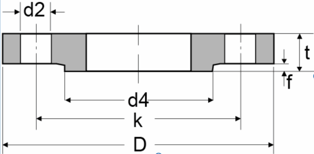
For each DN, DIN 2544 specifies:
- D – Outside diameter of flange
- K – Pitch circle diameter (PCD) / bolt circle diameter
- d₂ – Bore diameter (matches pipe OD with clearance)
- b – Flange thickness
- f – Height of raised face (if applicable)
- Number of bolt holes & bolt size (e.g., M16, M20, M24)
- Tolerances – per DIN 2768
DIN 2544 PN25 Plate Flange Dimensions
| Rated Diameter | O.D. of Pipe | Flange Dimension | Screw Dimension | Approx. Flange Weight | ||||||
| DN | ISO | DIN | d4 | D | t | f | K | No. of Holes | d2 | KG/PCS |
| 10 | 17.2 | 14 | 40 | 90 | – | 2 | 60 | 4 | 14 | 0.72 |
| 15 | 21.3 | 20 | 45 | 95 | 16 | 2 | 65 | 4 | 14 | 0.81 |
| 20 | 26.9 | 25 | 58 | 105 | 18 | 2 | 75 | 4 | 14 | 1.24 |
| 25 | 33.7 | 30 | 68 | 115 | 18 | 2 | 85 | 4 | 14 | 1.38 |
| 32 | 42.4 | 38 | 78 | 140 | 18 | 2 | 100 | 4 | 18 | 2.03 |
| 40 | 48.3 | 44.5 | 88 | 150 | 18 | 3 | 110 | 4 | 18 | 2.35 |
| 50 | 60.3 | 57 | 102 | 165 | 20 | 3 | 125 | 4 | 18 | 3.2 |
| 65 | 76.1 | – | 122 | 185 | 22 | 3 | 145 | 4 | 18 | 4.29 |
| 80 | 88.9 | – | 138 | 200 | 24 | 3 | 160 | 8 | 18 | 5.88 |
| 100 | 114.3 | 108 | 162 | 235 | 24 | 3 | 190 | 8 | 23 | 7.54 |
| 125 | 139.7 | 133 | 188 | 270 | 26 | 3 | 220 | 8 | 27 | 10.8 |
| 150 | 168.3 | 159 | 218 | 300 | 28 | 3 | 250 | 8 | 27 | 14.5 |
| 200 | 219.1 | 216 | 278 | 360 | 30 | 3 | 310 | 12 | 27 | 22.3 |
| 250 | 273 | 267 | 335 | 425 | 32 | 3 | 370 | 12 | 30 | 33.5 |
| 300 | 323.9 | 318 | 395 | 485 | 34 | 4 | 430 | 16 | 30 | 46.3 |
| 350 | 355.6 | 368 | 450 | 555 | 38 | 4 | 490 | 16 | 33 | 68 |
| 400 | 406.4 | 419 | 505 | 620 | 40 | 4 | 550 | 16 | 36 | 89.7 |
| 500 | 508 | 521 | 615 | 730 | 44 | 4 | 660 | 20 | 36 | 138 |
| 600 | 609.6 | 622 | 720 | 845 | – | 5 | 770 | 20 | 39 | – |
| 700 | 711.2 | 720 | 820 | 960 | – | 5 | 870 | 24 | 42 | – |
| 800 | 812.8 | 820 | 930 | 1085 | – | 5 | 990 | 24 | 48 | – |
| 900 | 914.4 | 920 | 1030 | 1185 | – | 5 | 1090 | 28 | 48 | – |
| 1000 | 1016 | 1020 | 1140 | 1320 | – | 5 | 1210 | 28 | 56 | – |
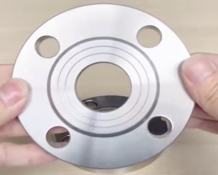
DIN 2544 Flange Types of Facing
- Form A: Flat Face (FF)
- Form B: Raised Face (RF), 2 mm height for PN ≤ 25
- Machined sealing surface: concentric or spiral serrated grooves (Ra 3.2–12.5 μm)
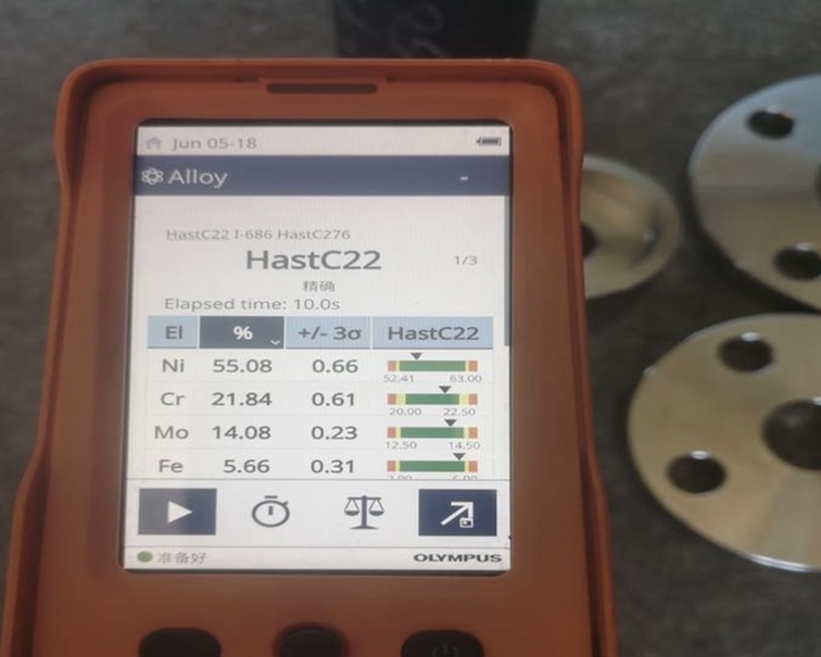
DIN 2544 Flange Materials
Per relevant DIN/EN standards:
- Carbon Steel: C22.8 (1.0460), P245GH, P250GH
- Stainless Steel: 1.4301 (304), 1.4404 (316L), 1.4571 (316Ti)
- Alloy Steel: 16Mo3, 13CrMo4-5
- Non-ferrous metals (bronze, CuNi) for seawater service
DIN 2544 Flange Gasket Compatibility
- DIN 2544 Form B → suitable for DIN EN 1514-1 Type I raised face gaskets
- Material selection depends on medium, temperature, and pressure”