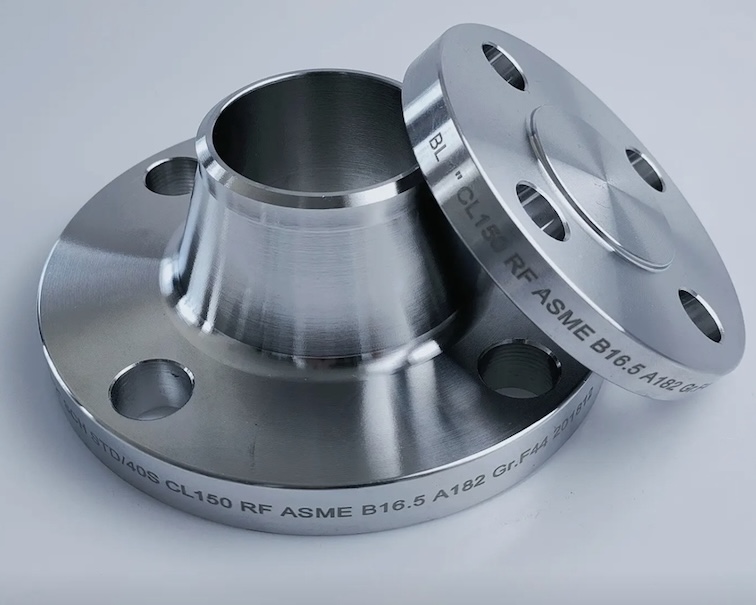
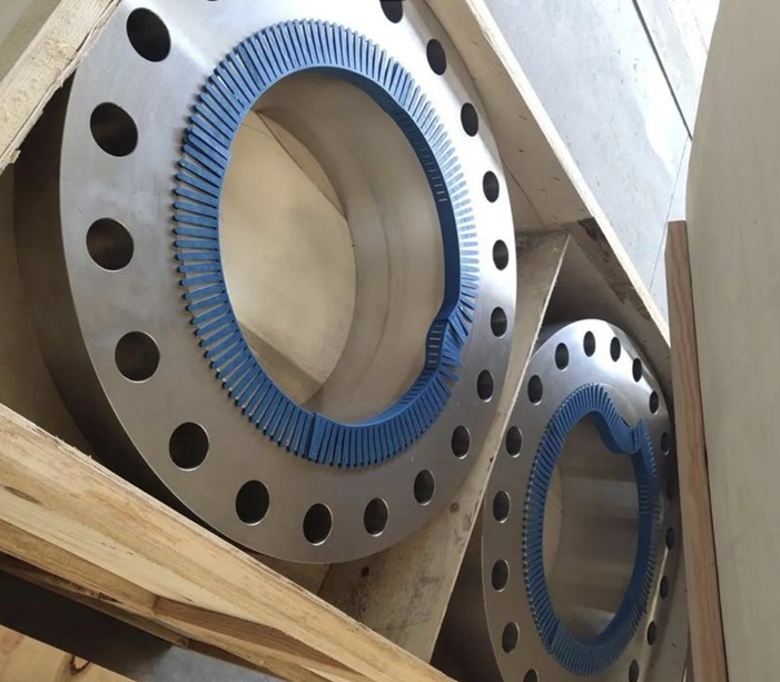
ASME B16.47 Series A Weld Neck Flanges & Blind Flange Manufacturer
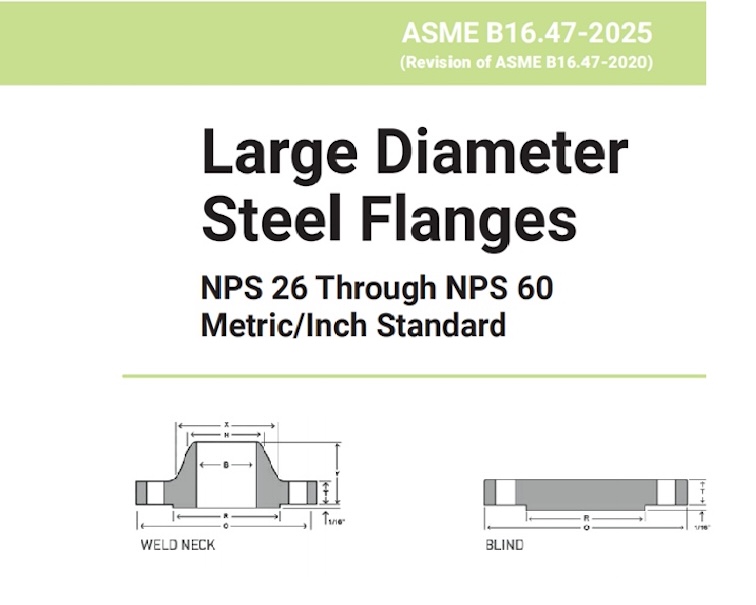
ASME B16.47 Series A specifies large-diameter steel flanges from NPS 26 to NPS 60, designed for demanding pressure pipelines. Series A flanges are the heavier and stronger version of the ASME B16.47 standard, featuring thicker sections and larger bolt circle diameters. These flanges are commonly used in oil & gas, refineries, chemical plants, and power generation facilities where maximum safety and durability are required.
The B16.47 standard is divided into Series A and Series B, and covers blind flange and welding neck flange. Below is a comparison chart of the differences between Series A & Series B:
While ASME B16.47 Series A has the same dimension requirment with MSS SP 44 standard.ASME B16.47 Series B has the same dimension requirment with API 605.
MSS SP-44 covers similar Class 150, 300, 400, 600, and 900 flanges for use with high strength pipe made from
materials having yield strength greater than 276 MPa (40,000 psi)
Types of Flanges Covered
| Type | Description | Notes |
|---|---|---|
| Series A | Formerly MSS SP-44 flanges | Thicker, heavier, and stronger; used in high-pressure, critical applications |
| Series B | Formerly API 605 flanges | Lighter and more compact; used in general piping and process industries |
This Standard covers pressure–temperature ratings,materials, dimensions, tolerances, marking, and testing For pipe flanges in sizes NPS 26 through NPS 60. Included are flanges with rating class designations 75, 150, 300, 400, 600, and 900 with requirements given in both SI (Metric) and U.S. Customary units, with diameter
Matrial selection for ASME B16.47 Flanges
| Material Group No. | Nominal Designation | Forgings | Castings | Plates [Note (1)] |
| 1.1 | C-Si | A105 | A216 Gr. WCB | A515 Gr. 70 |
| 1.1 | C-Mn-Si | A350 Gr. LF2 | … | A516 Gr. 70 |
| 1.1 | C-Mn-Si-V | A350 Gr. LF6 Cl. 1 | … | … |
| 1.1 | 3½Ni | A350 Gr. LF3 | … | … |
| 1.2 | C-Mn-Si-V | A350 Gr. LF6 Cl. 2 | … | … |
| 1.3 | C-Mn-Si | … | … | A516 Gr. 65 |
| 1.4 | C-Si | A350 Gr. LF1 Cl. 1 | … | A515 Gr. 60 |
| 1.4 | C-Mn-Si | … | … | A516 Gr. 60 |
| 1.5 | C-½Mo | A182 Gr. F1 | … | A204 Gr. A |
| 1.7 | ¼Cr-½Mo | A182 Gr. F2 | … | … |
| 1.9 | 1¼Cr-½Mn-Si | A182 Gr. F11 Cl. 2 | … | A387 Gr. 11 Cl. 2 |
| 1.1 | 2¼Cr-1Mo | A182 Gr. F22 Cl. 3 | A217 Gr. WC9 | A387 Gr. 22 Cl. 2 |
| 1.11 | 3Cr-1Mo | A182 F21 | … | A387 Gr. 21 Cl 2 |
| 1.13 | 5Cr-½Mo | A182 Gr. F5A | A217 Gr. C5 | … |
| 1.14 | 9Cr-1Mo | A182 Gr. F9 | A217 Gr. C12 | … |
| 1.15 | 9Cr-1Mo-V | A182 Gr. F91 Type 1 | A217 Gr. C12A | A387 Gr. 91 Cl. 2 |
| 1.17 | 1Cr-½Mo | A182 Gr. F12 Cl. 2 | … | … |
| 1.18 | 5Cr-½Mo | A182 Gr. F5 | … | … |
| 1.18 | 9Cr-2W-V | A182 Gr. F92 | … | … |
| 2.1 | 18Cr-8Ni | A182 Gr. F304 | A351 Gr. CF3 | A240 Gr. 304 |
| 2.1 | 18Cr-8Ni | A182 Gr. F304H | A351 Gr. CF8 | A240 Gr. 304H |
| 2.2 | 16Cr-12Ni-2Mo | A182 Gr. F316 | A351 Gr. CF3M | A240 Gr. 316 |
| 2.2 | 16Cr-12Ni-2Mo | A182 Gr. F316H | A351 Gr. CF8M | A240 Gr. 316H |
| 2.2 | 18Cr-13Ni-3Mo | A182 Gr. F317 | … | A240 Gr. 317 |
| 2.3 | 18Cr-8Ni | A182 Gr. F304L | … | A240 Gr. 304L |
| 2.3 | 16Cr-12Ni-2Mo | A182 Gr. F316L | … | A240 Gr. 316L |
| 2.3 | 18Cr-13Ni-3Mo | A182 Gr. F317L | … | … |
| 2.4 | 18Cr-10Ni-Ti | A182 Gr. F321 | … | A240 Gr. 321 |
| 2.4 | 18Cr-10Ni-Ti | A182 Gr. F321H | … | A240 Gr. 321H |
| 2.5 | 18Cr-10Ni-Cb | A182 Gr. F347 | … | A240 Gr. 347 |
| 2.5 | 18Cr-10Ni-Cb | A182 Gr. F347H | … | A240 Gr. 347H |
| 2.5 | 18Cr-10Ni-Cb | A182 Gr. F348 | … | A240 Gr. 348 |
| 2.5 | 18Cr-10Ni-Cb | A182 Gr. F348H | … | A240 Gr. 348H |
| 2.6 | 23Cr-12Ni | … | … | A240 Gr. 309H |
| 2.7 | 25Cr-20Ni | A182 Gr. F310H | … | A240 Gr. 310H |
| 2.8 | 20Cr-18Ni-6Mo | A182 Gr. F44 | A351 Gr. CK3MCuN | A240 Gr. S31254 |
| 2.13 | 22Cr-5Ni-3Mo-N | A182 Gr. F51 | A995 CD3MN (4A) | A240 Gr. S31803 |
| 2.13 | 22Cr-5Ni-3Mo-N | A182 Gr. F60 | … | … |
| 2.13 | 22Cr-5Ni-3Mo-N | … | … | A240 Gr. S32205 |
| 2.13 | 25Cr-5Ni-3Mo-2Cu | … | … | A240 Gr. S32550 |
| 2.13 | 25Cr-7Ni-4Mo-N | A182 Gr. F53 | … | A240 Gr. S32750 |
| 2.13 | 25Cr-7Ni-3.5Mo-N-Cu-W | A182 Gr. F55 | … | A240 Gr. S32760 |
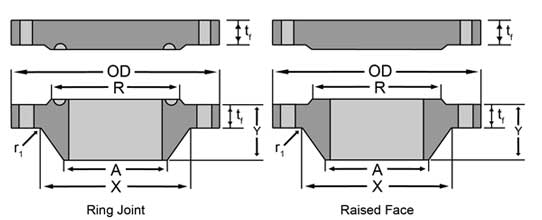
Facing Finish Requirements of ASME B16.47
- Raised Face (RF): 125–250 µin (3.2–6.3 µm) serrated finish
- RTJ (Ring Type Joint): Groove dimensions per ASME B16.20
- Flat Face (FF): Only for special applications
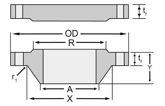
ASME B16.47 Series A Class 150 Flange Dimensions
| Nominal Size | Outside Diameter(OD) | Min. Thickness [Note1] – WNF (tf) | Min. Thickness [Note1] – Blind (tf) | Length Through Hub (Y) | Hub Dia. Base [Note2] (X) | Hub Dia. Top (A | Raised Face Dia. (R) | Drilling – Bolt Circle Dia | Drilling – No. of Bolt Holes | Drilling – Dia. of Bolt Hole | Dia. of Bolt | Min. Fillet Radius(r1) |
| 26 | 34.25 | 2.63 | 2.63 | 4.69 | 26.62 | 26 | 29.5 | 31.75 | 24 | 13⁄8 | 11⁄4 | 0.38 |
| 28 | 36.5 | 2.75 | 2.75 | 4.88 | 28.62 | 28 | 31.5 | 34 | 28 | 13⁄8 | 11⁄4 | 0.44 |
| 30 | 38.75 | 2.88 | 2.88 | 5.32 | 30.75 | 30 | 33.75 | 36 | 28 | 13⁄8 | 11⁄4 | 0.44 |
| 32 | 41.75 | 3.13 | 3.13 | 5.63 | 32.75 | 32 | 36 | 38.5 | 28 | 15⁄8 | 11⁄2 | 0.44 |
| 34 | 43.75 | 3.19 | 3.19 | 5.82 | 34.75 | 34 | 38 | 40.5 | 32 | 15⁄8 | 11⁄2 | 0.5 |
| 36 | 46 | 3.5 | 3.5 | 6.13 | 36.75 | 36 | 40.25 | 42.75 | 32 | 15⁄8 | 11⁄2 | 0.5 |
| 38 | 48.75 | 3.38 | 3.38 | 6.13 | 39 | 38 | 42.25 | 45.25 | 32 | 15⁄8 | 11⁄2 | 0.5 |
| 40 | 50.75 | 3.5 | 3.5 | 6.38 | 41 | 40 | 44.25 | 47.25 | 36 | 15⁄8 | 11⁄2 | 0.5 |
| 42 | 53 | 3.75 | 3.75 | 6.69 | 43 | 42 | 47 | 49.5 | 36 | 15⁄8 | 11⁄2 | 0.5 |
| 44 | 55.25 | 3.94 | 3.94 | 6.94 | 45 | 44 | 49 | 51.75 | 40 | 15⁄8 | 11⁄2 | 0.5 |
| 46 | 57.25 | 4 | 4 | 7.25 | 47.12 | 46 | 51 | 53.75 | 40 | 15⁄8 | 11⁄2 | 0.5 |
| 48 | 59.5 | 4.19 | 4.19 | 7.5 | 49.12 | 48 | 53.5 | 56 | 44 | 15⁄8 | 11⁄2 | 0.5 |
| 50 | 61.75 | 4.32 | 4.32 | 7.94 | 51.25 | 50 | 55.5 | 58.25 | 44 | 17⁄8 | 13⁄4 | 0.5 |
| 52 | 64 | 4.5 | 4.5 | 8.19 | 53.25 | 52 | 57.5 | 60.5 | 44 | 17⁄8 | 13⁄4 | 0.5 |
| 54 | 66.25 | 4.69 | 4.69 | 8.44 | 55.25 | 54 | 59.5 | 62.75 | 44 | 17⁄8 | 13⁄4 | 0.5 |
| 56 | 68.75 | 4.82 | 4.82 | 8.94 | 57.38 | 56 | 62 | 65 | 48 | 17⁄8 | 13⁄4 | 0.5 |
| 58 | 71 | 5 | 5 | 9.19 | 59.38 | 58 | 64 | 67.25 | 48 | 17⁄8 | 13⁄4 | 0.5 |
| 60 | 73 | 5.13 | 5.13 | 9.38 | 61.38 | 60 | 66 | 69.25 | 52 | 17⁄8 | 13⁄4 | 0.5 |
Dimensions are in inches.
1) The minimum flange thickness does not include the raised face thickness
2) This dimension is for the large end of hub, which may be straight or tapered.
3) Weldneck Bore/ID is to be specified by the purchaser
4) For other details and tolerances see specification.
ANSI/ASME B16.47 Series A Class 300 Flange Dimensions
| Nominal Size | Outside Diameter(OD) | Min. Thickness [Note1] – WNF (tf) | Min. Thickness [Note1] – Blind (tf) | Length Through Hub (Y) | Hub Dia. Base [Note2] (X) | Hub Dia. Top (A | Raised Face Dia. (R) | Drilling – Bolt Circle Dia | Drilling – No. of Bolt Holes | Drilling – Dia. of Bolt Hole | Dia. of Bolt | Min. Fillet Radius(r1) |
| 26 | 38.25 | 3.07 | 3.25 | 7.19 | 28.38 | 26 | 29.5 | 34.5 | 28 | 13/4 | 15/8 | 0.38 |
| 28 | 40.75 | 3.32 | 3.5 | 7.69 | 30.5 | 28 | 31.5 | 37 | 28 | 13/4 | 15/8 | 0.44 |
| 30 | 43 | 3.57 | 3.69 | 8.19 | 32.56 | 30 | 33.75 | 39.25 | 28 | 17/8 | 13/4 | 0.44 |
| 32 | 45.25 | 3.82 | 3.88 | 8.69 | 34.69 | 32 | 36 | 41.5 | 28 | 2 | 17/8 | 0.44 |
| 34 | 47.5 | 3.94 | 4.07 | 9.07 | 36.88 | 34 | 38 | 43.5 | 28 | 2 | 17/8 | 0.5 |
| 36 | 50 | 4.07 | 4.32 | 9.44 | 39 | 36 | 40.25 | 46 | 32 | 21/8 | 2 | 0.5 |
| 38 | 46 | 4.19 | 4.19 | 7.06 | 39.12 | 38 | 40.5 | 43 | 32 | 15/8 | 11/2 | 0.5 |
| 40 | 48.75 | 4.44 | 4.44 | 7.56 | 41.25 | 40 | 42.75 | 45.5 | 32 | 13/4 | 15/8 | 0.5 |
| 42 | 50.75 | 4.63 | 4.63 | 7.82 | 43.25 | 42 | 44.75 | 47.5 | 32 | 13/4 | 15/8 | 0.5 |
| 44 | 53.25 | 4.82 | 4.82 | 8.06 | 45.25 | 44 | 47 | 49.75 | 32 | 17/8 | 13/4 | 0.5 |
| 46 | 55.75 | 5 | 5 | 8.44 | 47.38 | 46 | 49 | 52 | 28 | 2 | 17/8 | 0.5 |
| 48 | 57.75 | 5.19 | 5.19 | 8.75 | 49.38 | 48 | 51.25 | 54 | 32 | 2 | 17/8 | 0.5 |
| 50 | 60.25 | 5.44 | 5.44 | 9.07 | 51.38 | 50 | 53.5 | 56.25 | 32 | 21/8 | 2 | 0.5 |
| 52 | 62.25 | 5.63 | 5.63 | 9.32 | 53.38 | 52 | 55.5 | 58.25 | 32 | 21/8 | 2 | 0.5 |
| 54 | 65.25 | 5.94 | 5.94 | 9.88 | 55.5 | 54 | 57.75 | 61 | 28 | 23/8 | 21/4 | 0.5 |
| 56 | 67.25 | 6 | 6 | 10.19 | 57.62 | 56 | 59.75 | 63 | 28 | 23/8 | 21/4 | 0.5 |
| 58 | 69.25 | 6.19 | 6.19 | 10.44 | 59.62 | 58 | 62 | 65 | 32 | 23/8 | 21/4 | 0.5 |
| 60 | 71.25 | 6.38 | 6.38 | 10.69 | 61.62 | 60 | 64 | 67 | 32 | 23/8 | 21/4 | 0.5 |
ANSI B16.47 Series A Class 400 Flange Dimensions
| Nominal Size | Outside Diameter(OD) | Min. Thickness [Note1] – WNF (tf) | Min. Thickness [Note1] – Blind (tf) | Length Through Hub (Y) | Hub Dia. Base [Note2] (X) | Hub Dia. Top (A | Raised Face Dia. (R) | Drilling – Bolt Circle Dia | Drilling – No. of Bolt Holes | Drilling – Dia. of Bolt Hole | Dia. of Bolt | Min. Fillet Radius(r1) |
| 26 | 38.25 | 3.5 | 3.88 | 7.62 | 28.62 | 26 | 29.5 | 34.5 | 28 | 17/8 | 13/4 | 0.44 |
| 28 | 40.75 | 3.75 | 4.12 | 8.12 | 30.81 | 28 | 31.5 | 37 | 28 | 2 | 17/8 | 0.5 |
| 30 | 43 | 4 | 4.38 | 8.62 | 32.94 | 30 | 33.75 | 39.25 | 28 | 21/8 | 2 | 0.5 |
| 32 | 45.25 | 4.25 | 4.56 | 9.12 | 35 | 32 | 36 | 41.5 | 28 | 21/8 | 2 | 0.5 |
| 34 | 47.5 | 4.38 | 4.81 | 9.5 | 37.19 | 34 | 38 | 43.5 | 28 | 21/8 | 2 | 0.56 |
| 36 | 50 | 4.5 | 5.06 | 9.88 | 39.38 | 36 | 40.25 | 46 | 32 | 21/8 | 2 | 0.56 |
| 38 | 47.5 | 4.88 | 4.88 | 8.12 | 39.5 | 38 | 40.75 | 44 | 32 | 17/8 | 13/4 | 0.56 |
| 40 | 50 | 5.12 | 5.12 | 8.5 | 41.5 | 40 | 43 | 46.25 | 32 | 2 | 17/8 | 0.56 |
| 42 | 52 | 5.25 | 5.25 | 8.81 | 43.62 | 42 | 45 | 48.25 | 32 | 2 | 17/8 | 0.56 |
| 44 | 54.5 | 5.5 | 5.5 | 9.18 | 45.62 | 44 | 47.25 | 50.5 | 32 | 21/8 | 2 | 0.56 |
| 46 | 56.75 | 5.75 | 5.75 | 9.62 | 47.75 | 46 | 49.5 | 52.75 | 36 | 21/8 | 2 | 0.56 |
| 48 | 59.5 | 6 | 6 | 10.12 | 49.88 | 48 | 51.5 | 55.25 | 28 | 23/8 | 21/4 | 0.56 |
| 50 | 61.75 | 6.19 | 6.25 | 10.56 | 52 | 50 | 53.62 | 57.5 | 32 | 23/8 | 21/4 | 0.56 |
| 52 | 63.75 | 6.38 | 6.44 | 10.88 | 54 | 52 | 55.62 | 59.5 | 32 | 23/8 | 21/4 | 0.56 |
| 54 | 67 | 6.69 | 6.75 | 11.38 | 56.12 | 54 | 57.88 | 62.25 | 28 | 25/8 | 21/2 | 0.56 |
| 56 | 69 | 6.88 | 6.94 | 11.75 | 58.25 | 56 | 60.12 | 64.25 | 32 | 25/8 | 21/2 | 0.56 |
| 58 | 71 | 7 | 7.12 | 12.06 | 60.25 | 58 | 62.12 | 66.25 | 32 | 25/8 | 21/2 | 0.56 |
| 60 | 74.25 | 7.31 | 7.44 | 12.56 | 62.38 | 60 | 64.38 | 69 | 32 | 27/8 | 23/4 | 0.56 |
ANSI B16.47 Series A Class 600 Flange Dimension
| Nominal Size | Outside Diameter(OD) | Min. Thickness [Note1] – WNF (tf) | Min. Thickness [Note1] – Blind (tf) | Length Through Hub (Y) | Hub Dia. Base [Note2] (X) | Hub Dia. Top (A | Raised Face Dia. (R) | Drilling – Bolt Circle Dia | Drilling – No. of Bolt Holes | Drilling – Dia. of Bolt Hole | Dia. of Bolt | Min. Fillet Radius(r1) |
| 26 | 40 | 4.25 | 4.94 | 8.75 | 29.44 | 26 | 29.5 | 36 | 28 | 2 | 17/8 | 0.5 |
| 28 | 42.25 | 4.38 | 5.19 | 9.25 | 31.62 | 28 | 31.5 | 38 | 28 | 21/8 | 2 | 0.5 |
| 30 | 44.5 | 4.5 | 5.5 | 9.75 | 33.94 | 30 | 33.75 | 40.25 | 28 | 21/8 | 2 | 0.5 |
| 32 | 47 | 4.62 | 5.81 | 10.25 | 36.12 | 32 | 36 | 42.5 | 28 | 23/8 | 21/4 | 0.5 |
| 34 | 49 | 4.75 | 6.06 | 10.62 | 38.31 | 34 | 38 | 44.5 | 28 | 23/8 | 21/4 | 0.56 |
| 36 | 51.75 | 4.88 | 6.38 | 11.12 | 40.62 | 36 | 40.25 | 47 | 28 | 25/8 | 21/2 | 0.56 |
| 38 | 50 | 6 | 6.12 | 10 | 40.25 | 38 | 41.5 | 45.75 | 28 | 23/8 | 21/4 | 0.56 |
| 40 | 52 | 6.25 | 6.38 | 10.38 | 42.25 | 40 | 43.75 | 47.75 | 32 | 23/8 | 21/4 | 0.56 |
| 42 | 55.25 | 6.62 | 6.75 | 11 | 44.38 | 42 | 46 | 50.5 | 28 | 25/8 | 21/2 | 0.56 |
| 44 | 57.25 | 6.81 | 7 | 11.38 | 46.5 | 44 | 48.25 | 52.5 | 32 | 25/8 | 21/2 | 0.56 |
| 46 | 59.5 | 7.06 | 7.31 | 11.81 | 48.62 | 46 | 50.25 | 54.75 | 32 | 25/8 | 21/2 | 0.56 |
| 48 | 62.75 | 7.44 | 7.69 | 12.44 | 50.75 | 48 | 52.5 | 57.5 | 32 | 27/8 | 23/4 | 0.56 |
| 50 | 65.75 | 7.75 | 8 | 12.94 | 52.88 | 50 | 54.5 | 60 | 28 | 31/8 | 3 | 0.56 |
| 52 | 67.75 | 8 | 8.25 | 13.25 | 54.88 | 52 | 56.5 | 62 | 32 | 31/8 | 3 | 0.56 |
| 54 | 70 | 8.25 | 8.56 | 13.75 | 57 | 54 | 58.75 | 64.25 | 32 | 31/8 | 3 | 0.56 |
| 56 | 73 | 8.56 | 8.88 | 14.25 | 59.12 | 56 | 60.75 | 66.75 | 32 | 33/8 | 31/4 | 0.62 |
| 58 | 75 | 8.75 | 9.12 | 14.56 | 61.12 | 58 | 63 | 68.75 | 32 | 33/8 | 31/4 | 0.62 |
| 60 | 78.5 | 9.19 | 9.56 | 15.31 | 63.38 | 60 | 65.25 | 71.75 | 28 | 35/8 | 31/2 | 0.69 |
ASME B16.47 Series A Class 900 Flange Dimensions
| Nominal Size | Outside Diameter(OD) | Min. Thickness [Note1] – WNF (tf) | Min. Thickness [Note1] – Blind (tf) | Length Through Hub (Y) | Hub Dia. Base [Note2] (X) | Hub Dia. Top (A | Raised Face Dia. (R) | Drilling – Bolt Circle Dia | Drilling – No. of Bolt Holes | Drilling – Dia. of Bolt Hole | Dia. of Bolt | Min. Fillet Radius(r1) |
| 26 | 42.75 | 5.5 | 6.31 | 11.25 | 30.5 | 26 | 29.5 | 37.5 | 20 | 27/8 | 23/4 | 0.44 |
| 28 | 46 | 5.62 | 6.75 | 11.75 | 32.75 | 28 | 31.5 | 40.25 | 20 | 31/8 | 3 | 0.5 |
| 30 | 48.5 | 5.88 | 7.18 | 12.25 | 35 | 30 | 33.75 | 42.75 | 20 | 31/8 | 3 | 0.5 |
| 32 | 51.75 | 6.25 | 7.62 | 13 | 37.25 | 32 | 36 | 45.5 | 20 | 33/8 | 31/4 | 0.5 |
| 34 | 55 | 6.5 | 8.06 | 13.75 | 39.62 | 34 | 38 | 48.25 | 20 | 35/8 | 31/2 | 0.56 |
| 36 | 57.5 | 6.75 | 8.44 | 14.25 | 41.88 | 36 | 40.25 | 50.75 | 20 | 35/8 | 31/2 | 0.56 |
| 38 | 57.5 | 7.5 | 8.5 | 13.88 | 42.25 | 38 | 43.25 | 50.75 | 20 | 35/8 | 31/2 | 0.75 |
| 40 | 59.5 | 7.75 | 8.81 | 14.31 | 44.38 | 40 | 45.75 | 52.75 | 24 | 35/8 | 31/2 | 0.81 |
| 42 | 61.5 | 8.12 | 9.12 | 14.62 | 46.31 | 42 | 47.75 | 54.75 | 24 | 35/8 | 31/2 | 0.81 |
| 44 | 64.88 | 8.44 | 9.56 | 15.38 | 48.62 | 44 | 50 | 57.62 | 24 | 37/8 | 33/4 | 0.88 |
| 46 | 68.25 | 8.88 | 10.06 | 16.18 | 50.88 | 46 | 52.5 | 60.5 | 24 | 41/8 | 4 | 0.88 |
| 48 | 70.25 | 9.19 | 10.38 | 16.5 | 52.88 | 48 | 54.5 | 62.5 | 24 | 41/8 | 4 | 0.94 |
Flanges ASME B16.47 – Weights
| Flange ASME B16.47-A (MSS SP 44) | ||||||||
| NPS SIZE | CLASS 150 | CLASS 300 | CLASS 600 | CLASS 900 | ||||
| WELDING NECK | BLIND | WELDING NECK | BLIND | WELDING NECK | BLIND | WELDING NECK | BLIND | |
| 22 | 109 | 162 | 204 | 284 | 310 | 437 | ||
| 26 | 154 | 321 | 291 | 477 | 450 | 777 | 890 | 1100 |
| 28 | 175 | 380 | 352 | 584 | 506 | 909 | 1055 | 1350 |
| 30 | 204 | 450 | 405 | 685 | 575 | 1074 | 1230 | 1610 |
| 32 | 254 | 560 | 465 | 793 | 642 | 1253 | 1480 | 1940 |
| 34 | 273 | 625 | 523 | 919 | 705 | 1427 | 1750 | 2310 |
| 36 | 321 | 760 | 580 | 1072 | 800 | 1665 | 1997 | 2660 |
| 38 | 358 | 830 | 324 | 900 | 674 | 1509 | 2000 | 2690 |
| 40 | 386 | 925 | 391 | 1066 | 725 | 1695 | 2161 | 2950 |
| 42 | 442 | 1080 | 428 | 1206 | 895 | 2028 | 2379 | 3280 |
| 44 | 491 | 1230 | 485 | 1378 | 951 | 2246 | 3321 | 3810 |
| 46 | 525 | 1345 | 559 | 1570 | 1055 | 2543 | 3224 | 4430 |
| 48 | 580 | 1520 | 597 | 1745 | 1247 | 2951 | 3500 | 4860 |
| 50 | 624 | 1668 | 674 | 1983 | 1423 | 3381 | ||
| 52 | 689 | 1867 | 728 | 2194 | 1493 | 3682 | ||
| 54 | 760 | 2088 | 871 | 2538 | 1637 | 4091 | ||
| 56 | 845 | 2308 | 921 | 2728 | 1843 | 4585 | ||
| 58 | 923 | 2554 | 968 | 2975 | 1954 | 4986 | ||
| 60 | 971 | 2765 | 1032 | 3250 | 2353 | 5750 | ||
Weight in “Kg”
ASME B16.47 Series A Flange Dimension download
| Welding Neck Flanges | Blind Flanges |
|---|---|
| ASME B16.47 Series A Class 150 Welding Neck Flanges | ASME B16.47 Series A Class 150 Blind Flanges |
| ASME B16.47 Series A Class 300 | ASME B16.47 Series A Class 300 Blind Flanges |
| ASME B16.47 Series A Class 400 | ASME B16.47 Series A Class 400 Blind Flanges |
| ASME B16.47 Series A Class 600 | ASME B16.47 Series A Class 600 Blind Flanges |
| ASME B16.47 Series A Class 900 | ASME B16.47 Series A Class 900 Blind Flanges |
Example Product Designation
ASME B16.47 Series A Weld Neck Flange
NPS 42" Class 600 RF
Material: ASTM A182 F316L
Qty: 6 pcs
Certificate: EN 10204 3.1
Download ASME B16.47 2025 Standard latest edition
Related Products
- ASME B16.47 Series B Flanges
- ASME B16.5 Flanges
- ASME B16.36 Orifice Flanges
- ASME B16.48 Spectacle Blinds
- API 6A Flanges
- EN 1092-1 Type 11 Weld Neck Flanges