ASME B16.11 Forged Steel Fittings Specification
ASME B16.11 covers the requirements for forged steel fittings that are used in high-pressure piping systems. These fittings are manufactured by forging solid steel bars and are supplied in socket weld and threaded (screwed) types, ensuring leak-proof performance in oil & gas, petrochemical, power, and marine industries.
Standard Overview
- Standard: ASME B16.11 – Forged Steel Fittings, Socket-Welding and Threaded
- Type: Socket Weld Fittings & Threaded Fittings
- Pressure Ratings: Class 2000, 3000, 6000, 9000
- Size Range: ½” to 4” (DN15 – DN100)
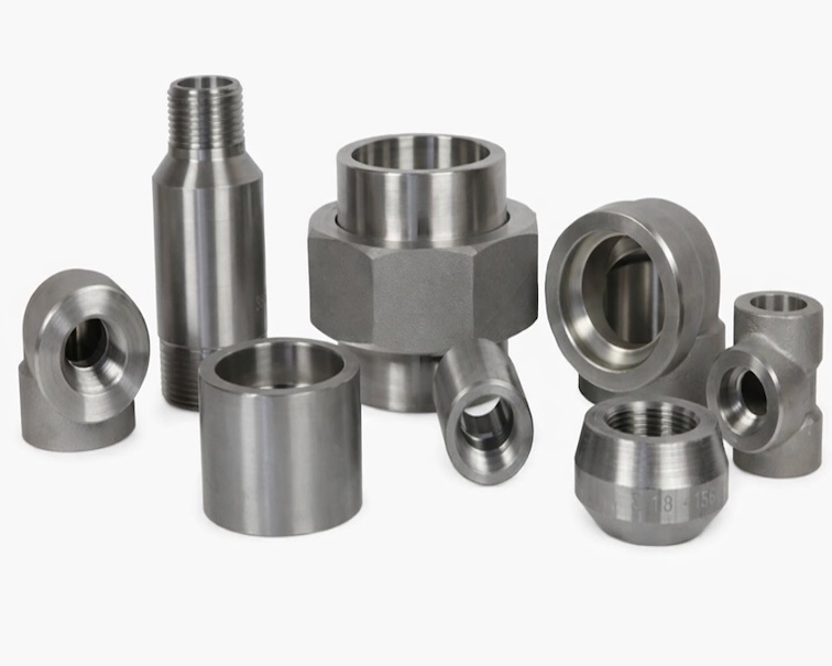
Forged Steel Fittings
Forged steel fittings named by their manufacturing processes forging, which to heat the carbon or alloy steel in a transforming temperature and modes the heated parts into the desired shape. Then use machining process to make a forged steel fittings.
Forged pipe fittings is in high quality which with higher strength and could bear high pressure. To this fittings you should pay attention to have a uniform wall thickness since they have to be through threading process or machined to socket weld end.
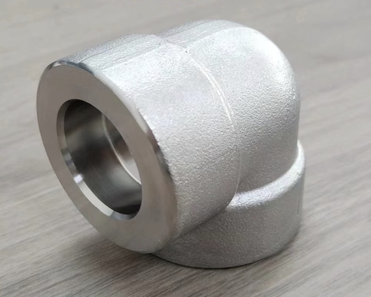
Socket Weld Fitting
A Socket Weld Fitting is a type of high-pressure forged pipe fitting used to connect pipes by inserting the pipe into a recessed area (socket) of the fitting and then applying a fillet weld around the joint. This method provides a strong, leak-proof, and permanent connection, making socket weld fittings suitable for small-bore, high-pressure piping systems.
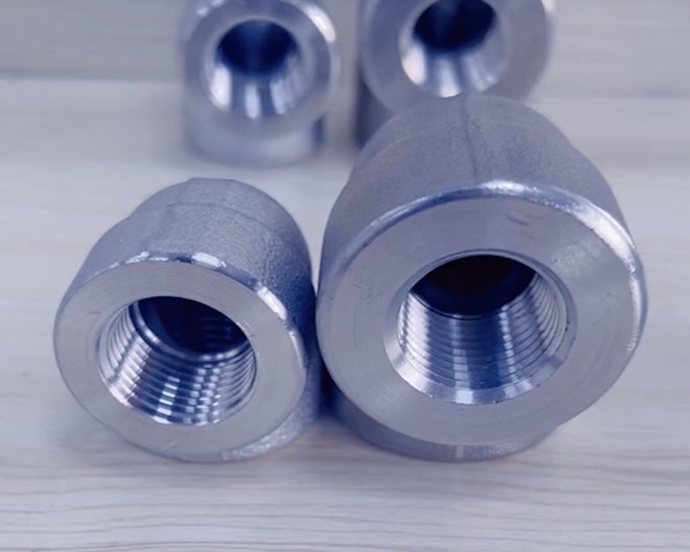
Threaded Fititngs
Threaded fittings (also called screwed fittings) are forged steel pipe fittings with internal or external threads used to connect pipes without welding. They rely on tapered threads (NPT / BSP) to create a mechanical joint, making them easy to assemble and disassemble. Threaded fittings are widely used in low to medium pressure piping systems where welding is not practical.
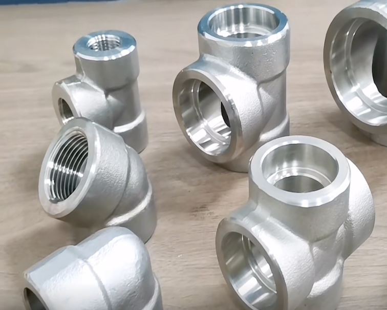
ASME B16.11 Forged Pipe Fitting Types
| Fitting Description | Socket-Welding – 3000 | Socket-Welding – 6000 | Socket-Welding – 9000 | Threaded – 2000 | Threaded – 3000 | Threaded – 6000 |
| 45-deg, 90-deg elbows | ¹⁄₈–4 | ¹⁄₈–2 | ½–2 | ¹⁄₈–4 | ¹⁄₈–4 | ¹⁄₈–4 |
| Tees, crosses | ¹⁄₈–4 | ¹⁄₈–2 | ½–2 | ¹⁄₈–4 | ¹⁄₈–4 | ¹⁄₈–4 |
| Couplings, half-couplings, caps, bosses | ¹⁄₈–4 | ¹⁄₈–2 | ½–2 | … | ¹⁄₈–4 | ¹⁄₈–4 |
| Couplets | ¼–4 | ¼–4 | … | … | ¼–4 | ¼–4 |
| Street elbows | … | … | … | … | ¹⁄₈–2 | ¹⁄₈–2 |
| Square, hex, round plug [Note (1)] | … | … | … | ¹⁄₈–4 | ¹⁄₈–4 | ¹⁄₈–4 |
| Hex, and flush bushing [Note (1)] | … | … | … | ¼–4 | ¼–4 | ¼–4 |
Special Fitting
Pipe fittings with special threads or special flares can be manufactured upon negotiation between the supplier and the buyer. These fittings shall be considered to be in particular conformity to the standard if they are properly marked (see Chapter 4 in ASME B16.11) and comply with all other provisions of this standard.
Welding
Installation welding requirements are outside the scope of this standard. Installation welding shall be in accordance with the applicable piping code or the operating procedures of the piping system in which the fitting is installed.
Pressure Rating for ASME B16.11 Forged Pipe Fittings
These fittings are designated as Class 2000, 3000, and 6000 for threaded end fittings and Class 3000, 6000, and 9000 for socket-weld end fittings.
Basis of Rating
The schedule of pipe corresponding to each Class designation of fittings for rating purposes is shown in below table. Design temperature and other service condition shall be limited as provided by the applicable piping code or regulation for the material of construction of the fitting. With these limits, it defines the minimum pipe wall thickness.
| Class Designation of Fitting | Type of Fitting | Schedule No. | Wall Designation |
|---|---|---|---|
| 2000 | Threaded | 80 | XS |
| 3000 | Threaded | 160 | … |
| 6000 | Threaded | … | XXS |
| 3000 | Socket-welding | 80 | XS |
| 6000 | Socket-welding | 160 | … |
| 9000 | Socket-welding | … | XXS |
NOTE: (1) This table is not intended to restrict the use of pipe of thinner or thicker wall with fittings. Pipe actually used may be thinner or thicker in nominal wall than that shown in this table. When thinner pipe is used, its strength may govern the rating. When thicker pipe is used (e.g., for mechanical strength), the strength of the fitting governs the rating.
Minimum Wall Thickness Tolerance
Typically 12.5%, minimum wall thickness shall not less than this value.
Non-standard pipe wall thickness
Since ANSI/ASME B36.10 M does not include pipe wall thickness series 160 (SCH160) nor extra strong thicknesses for NPS 1/8, NPS 1/4 and NPS 3/8, the value listed in below table can be used as the nominal wall thickness of the pipe when determining the rating.
Combination End Fitting
Pipe fittings composed of socket welding and threaded ends shall be graded according to the shape of the end with a minimum rating from table 1.
Pressure Test Capability
This standard does not require a pressure test, but the fittings shall be able to withstand the hydrostatic test pressure required by the applicable pipe code to accommodate seamless pipe of material equivalent to the fittings forging and of the schedule or wall thickness associated with the fittings grade and end connection of table 2.
ASME B16.11 Fittings Dimensions and Types
The specification code for the fitting is the nominal diameter of thread or socket weld connection. NPS, followed by a dimensionless number, is the designation for nominal fitting size. NPS is related to the reference nominal diameter, DN, used in international standard.
| DN | NPS |
|---|---|
| 6 | ¹⁄₈ |
| 8 | ¼ |
| 10 | ³⁄₈ |
| 15 | ½ |
| 20 | ¾ |
| 25 | 1 |
| 32 | 1¼ |
| 40 | 1½ |
| 50 | 2 |
| 65 | 2½ |
| 80 | 3 |
| 100 | 4 |
3.2 Reducing Fitting Size
For reducing tee and cross, the largest run opening should be given first, followed by the opening size at the opposite end. If the pipe fitting is a tee, the branch pipe size is given last. If the pipe fitting is a cross, the third dimension shall be the largest pipe opening, and then its relative opening specification.
Marking
Each fitting shall be permanently marked with the required identification by raised lettering and / or stamping, electro-etching, or vibro-tool marking on the collar portion, raised pad, or raised boss portion of the forging. Cylindrical fittings shall be marked on the O.D. or end of the fitting in a location such that the marking will not be obliterated as a result of welding installation. The marking of bushing and plugs is not required by this standard.
Specific Marking
The Specific marks should include (but are not limited to) the following:
a. Manufacturer’s Name or Trademark
Materials shall be in accordance with applicable ASME pipe fittings A234, A403, A420 or B366, or other applicable ASME forgings specifications A105, A182, A350, B160, B164 or ASME/ANSI B16.34 Table 1 (see section 5.1).
b. Material Identification.
c. Product Conformance.
The fittings in Section 1.1.1 shall be marked in accordance with the ASME Pipe Fitting Specification (eg “WP_”) or the symbol “B16” to indicate compliance with this standard.
Replaceable fittings marked with ASME forging marks (A105, A182, A350, etc.) in Section 1.1.2 shall not be marked B16.
Replaceable fittings marked with ASME fittings (A234, A403, A420, and B366) in Section 1.1.2 shall be marked with the serial number of the ASTM specification applicable to special or non-standard fittings.
d. Class Designation
According to the applicable situation, it can be divided into 2000, 3000, 6000 or 9000. Alternatives the designation 2M, 3M, 6M or 9M may also be used depending on the application, where M is 1000.
e. Size
Material Standards Referred for forged fittings
Fittings shall be made of materials consisting of forgings, bar, seamless pipe, or seamless tubular products. These materials shall conform to the requirements for the WP seamless construction materials of ASTM Fitting Specifications A234/A234M, A403/A403M, A420/A420M, A815/A815M, or B366, or ASTM Forging Specifications A105/A105M, A182/A182M, A350/A350M, B462, or B564.
Common Forged Materials for ASME B16.11 Fittings
| Material Type | ASTM / ASME Specification | Typical Grades |
| Carbon Steel | ASTM A105 / ASME SA105 | A105 |
| Low-Temperature Carbon Steel | ASTM A350 / ASME SA350 | LF2, LF3 |
| Alloy Steel | ASTM A182 / ASME SA182 | F1, F5, F9, F11, F22, ASTM A182 F91 |
| Stainless Steel | ASTM A182 / ASME SA182 | F304, F304L, F316, F316L, F321, F347 |
| Duplex & Super Duplex Stainless Steel | ASTM A182 / ASME SA182 | A182 F51 (UNS S31803), F53 (S32750), F55 (S32760) |
| Nickel Alloy | ASTM B564 | Inconel 600, 625, 800, Monel 400, Hastelloy C22 / C276 |
| Copper Nickel Alloy | ASTM B151 / ASTM B466 | C70600 (90/10 CuNi), C71500 (70/30 CuNi) |
| Aluminium Bronze | ASTM B150 | C95400, C95500 |
Tees, elbows, and crosses shall not be machined directly from bar stock
ASME B16.11 Fittings DIMENSIONS
SCREWED NPT ELBOW, TEE, CROSS, CAP & COUPLING B16.11
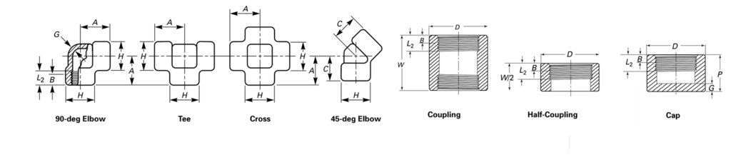
| SIZE | CENTER TO END 90 ELBOW, TEE AND CROSS A | CENTER TO END 45 ELBOW C | OUTSIDE DIAMETER OF BAND H | MINIMUM WALL THICKNESS G | THREAD LENGTH MINIMUM | END TO END W | END TO END W2 | END TO END CAPS P | OUTSIDE DIAMETER COUPLING, CAP D | END THICKNESS MIN CAP G | ||||||||
| CLASS | CLASS | CLASS | CLASS | 3000 & 6000 | 3000 & 6000 | CLASS | CLASS | CLASS | ||||||||||
| 3000 | 6000 | 3000 | 6000 | 3000 | 6000 | 3000 | 6000 | B | L2 | 3000 | 6000 | 3000 | 6000 | 3000 | 6000 | |||
| 6 | 21 | 25 | 17 | 19 | 22 | 25 | 3.18 | 6.35 | 6.4 | 6.7 | 32 | 16 | 19 | 22 | 16 | 22 | 4.8 | 6.4 |
| 8 | 25 | 28 | 19 | 22 | 25 | 33 | 3.30 | 6.60 | 8.1 | 10.2 | 35 | 17 | 25 | 27 | 19 | 25 | 4.8 | 6.4 |
| 10 | 28 | 33 | 22 | 25 | 33 | 38 | 3.51 | 6.98 | 9.1 | 10.4 | 48 | 24 | 32 | 27 | 22 | 32 | 4.8 | 6.4 |
| 15 | 33 | 38 | 25 | 28 | 38 | 46 | 4.09 | 8.15 | 10.9 | 13.6 | 48 | 24 | 32 | 33 | 28 | 38 | 6.4 | 7.9 |
| 20 | 38 | 44 | 28 | 33 | 46 | 56 | 4.32 | 8.53 | 12.7 | 13.9 | 51 | 25 | 37 | 38 | 35 | 44 | 6.4 | 7.9 |
| 25 | 44 | 51 | 33 | 35 | 56 | 62 | 4.98 | 9.93 | 14.7 | 17.3 | 60 | 30 | 41 | 43 | 44 | 57 | 9.7 | 11.2 |
| 32 | 51 | 60 | 35 | 43 | 62 | 75 | 5.28 | 10.59 | 17.0 | 18.0 | 67 | 33 | 44 | 46 | 57 | 64 | 9.7 | 11.2 |
| 40 | 60 | 64 | 43 | 44 | 75 | 84 | 5.56 | 11.07 | 17.8 | 18.4 | 79 | 39 | 44 | 48 | 64 | 76 | 11.2 | 12.7 |
| 50 | 64 | 83 | 44 | 52 | 84 | 102 | 7.14 | 12.09 | 19.0 | 19.2 | 86 | 43 | 48 | 51 | 76 | 92 | 12.7 | 15.7 |
| 65 | 83 | 95 | 52 | 64 | 102 | 121 | 7.65 | 15.29 | 23.6 | 28.9 | 92 | 46 | 60 | 64 | 92 | 108 | 15.7 | 19.0 |
| 80 | 95 | 106 | 64 | 79 | 121 | 146 | 8.84 | 16.64 | 25.9 | 30.5 | 108 | 54 | 65 | 68 | 108 | 127 | 19.0 | 22.4 |
| 100 | 114 | 114 | 79 | 79 | 152 | 152 | 11.18 | 18.67 | 27.7 | 33.0 | 121 | 60 | 68 | 75 | 140 | 159 | 22.4 | 28.4 |
SCREWED, NPT HEX PLUGS, BUSHES & NIPPLES B16.11 & BS3799
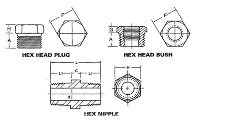
Dimensions mm
| SIZE | MIN LENGTH | PLUGS & BUSHES | HEX NIPPLES (BS 3799) | |||||||
| WIDTH FLATS | HEX HEIGHT | |||||||||
| F | BUSH | PLUG | ||||||||
| A | G | H | C | L1 | L | D (3000 lb) | D (6000 lb) | H | ||
| 6 | 10 | 11.11 | 6 | 6 | 10 | 26 | 5 | 2 | 11 | |
| 8 | 11 | 15.88 | 3 | 6 | 6 | 15 | 36 | 8 | 6 | 15 |
| 10 | 13 | 17.46 | 4 | 8 | 8 | 16 | 40 | 11 | 8 | 18 |
| 15 | 14 | 22.23 | 5 | 8 | 8 | 20 | 48 | 14 | 11 | 22 |
| 20 | 16 | 26.99 | 6 | 10 | 10 | 21 | 52 | 19 | 13 | 27 |
| 25 | 19 | 34.93 | 6 | 10 | 10 | 25 | 60 | 24 | 17 | 35 |
| 32 | 21 | 44.45 | 7 | 14 | – | – | – | – | – | – |
| 40 | 21 | 50.80 | 8 | 16 | 16 | 26 | 68 | 38 | 30 | 50 |
| 50 | 22 | 63.50 | 9 | 18 | 17 | 27 | 71 | 49 | 39 | 62 |
| 65 | 27 | 76.20 | 10 | 19 | – | – | – | – | – | – |
| 80 | 28 | 88.90 | 10 | 21 | – | – | – | – | – | – |
| 100 | 32 | 117.48 | 13 | 25 | – | – | – | – | – | – |
SOCKET WELD FITTINGS Dimension B16.11
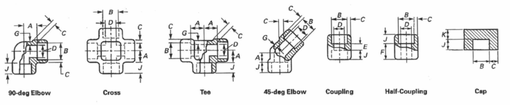
Dimensions in mm
| SIZE | BORE B | BORE D MAX/MIN CLASS | SOCKET WALL C MIN CLASS | BODY WALL G MIN CLASS | SOCKET DEPTH J MIN | CENTRE TO BOTTOM OF SOCKET A | LAYING LENGTH | END WALL | ||||||||
| 90 ELBOWS, TEES CROSSES CLASS | 45 ELBOWS CLASS | COUP- LING E | COUP- LING F | THICKNESS K MIN CLASS | ||||||||||||
| MAX/MIN | 3000 | 6000 | 3000 | 6000 | 3000 | 6000 | 3000 | 6000 | 3000 | 6000 | 3000 | 6000 | ||||
| 6 | 11.2/10.8 | 7.6/6.1 | 4.8/3. 2 | 3.18 | 3.43 | 2:41 | 3.15 | 9.5 | 11.00 | 11.00 | 8.00 | 8.00 | 6.5 | 16.0 | 4.8 | 6.4 |
| 8 | 14.6/14.2 | 10.0/8.5 | 7.1/5.6 | 3.30 | 4.01 | 3.02 | 3.68 | 9.5 | 11.00 | 13.50 | 8.00 | 8.00 | 6.5 | 16.0 | 4.8 | 6.4 |
| 10 | 18.0/17.6 | 13.3/11.8 | 9.9/8.4 | 3.50 | 4.37 | 3.20 | 4.01 | 9.5 | 13.50 | 15.50 | 8.00 | 11.00 | 6.5 | 17.5 | 4.8 | 6.4 |
| 15 | 22.2/21.8 | 16.6/15.0 | 12.5/11.0 | 4.09 | 5.18 | 3.73 | 4.78 | 9.5 | 15.50 | 19.00 | 11.00 | 12.50 | 9.5 | 22.5 | 6.4 | 7.9 |
| 20 | 27.6/27.2 | 21.7/20.2 | 16.3/14.8 | 4.27 | 6.04 | 3.91 | 5.56 | 12.5 | 19.00 | 22.50 | 13.00 | 14.00 | 9.5 | 24.0 | 6.4 | 7.9 |
| 25 | 34.3/33.9 | 27.4/25.9 | 21.5/19.9 | 4.98 | 6.93 | 4.55 | 6.35 | 12.5 | 22.50 | 27.00 | 14.00 | 17.50 | 12.5 | 28.5 | 9.6 | 11.2 |
| 32 | 43.1/42.7 | 35.8/34.3 | 30.2/28.7 | 5.28 | 6.93 | 4.85 | 6.35 | 12.5 | 27.00 | 32.00 | 17.50 | 20.50 | 12.5 | 30.0 | 9.6 | 11.2 |
| 40 | 49.2/48.8 | 41.6/40.1 | 34.7/33.2 | 5.54 | 7.80 | 5.08 | 7.14 | 12.5 | 32.00 | 38.00 | 20.50 | 25.50 | 12.5 | 32.0 | 11.2 | 12.7 |
| 50 | 61.7/61.2 | 53.3/51.7 | 43.6/42.1 | 6.04 | 9.50 | 5.54 | 8.74 | 16.0 | 38.00 | 41.00 | 25.50 | 28.50 | 19.0 | 41.0 | 12.7 | 15.7 |
| 65 | 74.4/73.9 | 64.2/61.2 | – | 7.67 | – | 7.01 | – | 16.0 | 41.00 | – | 28.50 | – | 19.0 | 43.0 | 15.7 | 19.0 |
| 80 | 90.3/89.8 | 79.4/76.4 | – | 8.30 | – | 7.62 | – | 16.0 | 57.00 | – | 32.00 | – | 19.0 | 44.5 | 19.0 | 22.4 |
| 100 | 115.7/115.2 | 103.8/100.7 | – | 9.35 | – | 8.56 | – | 19.0 | 66.50 | – | 41.00 | – | 19.0 | 48.0 | 22.4 | 28.4 |
ASME B16.11 Fittings WORKING PRESSURES
Possible Temperature Limitations
| Nominal Pressure Ratings | TEMPERATURE ºC | ||||||||||||||||||
| 38 | 66 | 93 | 121 | 149 | 177 | 204 | 232 | 260 | 288 | 316 | 343 | 371 | 399 | 427 | 427* | 482* | 510* | 538* | |
| 3000lb | 20670 | 20359 | 20084 | 19808 | 19602 | 19360 | 19119 | 18706 | 17948 | 16949 | 15915 | 14813 | 13504 | 12229 | 10507 | 8612 | 6373 | 4409 | 2445 |
| 6000lb | 41340 | 40754 | 40168 | 39617 | 39232 | 38756 | 38239 | 37412 | 37412 | 33933 | 31831 | 29627 | 27008 | 24459 | 21014 | 17225 | 12780 | 8853 | 4926 |
| Non-shock Working Pressures tabulated in kPa | |||||||||||||||||||
Download ASME B16.11-21 latest edition PDF
Types of Forged Fittings Covered
Socket Weld Fittings
- 90° Socket Weld Elbow
- 45° Socket Weld Elbow bow
- Socket Weld Tee
- Socket Weld Cross
- Socket Weld Half Coupling / Full Coupling
- Socket Weld Cap
- Socket Weld Union
Threaded Fittings
- 90° Threaded Elbow (Female x Female / Male x Female)
- Threaded Tee
- Threaded Cross
- Thread Plug (Hex / Square)
- Thresd Bushing
- Thread oupling
- Thread Union
Testing and Inspection
- Hydrostatic and Nondestructive Testing (NDT) as required by material specification
- Dimensional Inspection according to ASME B16.11
- Heat Treatment: Normalizing, Quenching & Tempering, or Solution Annealing as per ASTM grade
- Marking: Each fitting must include:
- Manufacturer’s name or trademark
- Material grade
- Pressure class
- Size
- Heat number
ASME B16.11 vs ASME B16.9
| Item | ASME B16.11 | ASME B16.9 |
|---|---|---|
| Fitting Type | Forged | Butt weld |
| Size Range | Up to 4″ | 1/2″ and above |
| Pressure Rating | Very high | Based on pipe |
| End Connection | SW / Threaded | Butt weld |
ASME B16.11 forged steel fittings provide reliable performance for high-pressure and high-temperature piping systems. With precise dimensions, high pressure ratings, and compatibility with multiple material grades, these fittings are widely trusted across oil & gas, power, and chemical industries.
For technical support, pricing, and fast delivery, contact a trusted ASME B16.11 forged fittings supplier today.