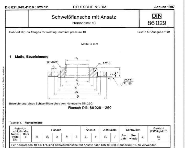
DIN 86029 PN10 Hubbed Slip On Flanges Manufacturer
DIN 86029 PN10 Hubbed Slip-On Flanges for Welding are a specific type of pipe flange standardized under German DIN norms, primarily used in marine engineering, shipbuilding, and related water systems.
DIN 86029 Standard & Scope
- Standard: DIN 86029
- Application: Typically used for welding to the pipe end, forming a tight, secure joint.
- Industry: Marine systems, ship piping, seawater pipelines, and industrial water systems.
DIN 86029 Pressure Rating
- PN10 → Nominal Pressure 10 bar (≈ 145 psi) at 20 °C.
- Suitable for low to medium pressure pipelines.
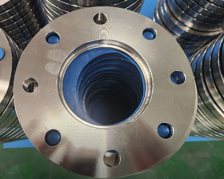
DIN 86029 Flange type
- Hubbed Slip-On Flange for Welding:
- Has a short cylindrical hub.
- Slips over the pipe end and is welded both inside and outside (fillet welds).
- Ensures strength and leak-tightness.
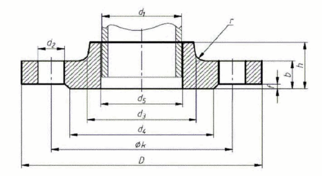
DIN 86029 Dimensions
DIN 86029 specifies DN (nominal diameter) sizes usually from DN 10 up to DN 600.
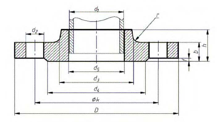
Main dimensions per standard include:
- D – Outside diameter
- K – Bolt circle diameter
- d₂ – Hub bore diameter (matching pipe OD)
- b – Flange thickness
- f – Raised face height (if applicable)
- Number of bolt holes & bolt size per PN10 table.
Example for DN 100, PN10 (approximate, check standard for exact):
- D: 220 mm
- K: 180 mm
- b: 18 mm
- Bolt holes: 8 × M16
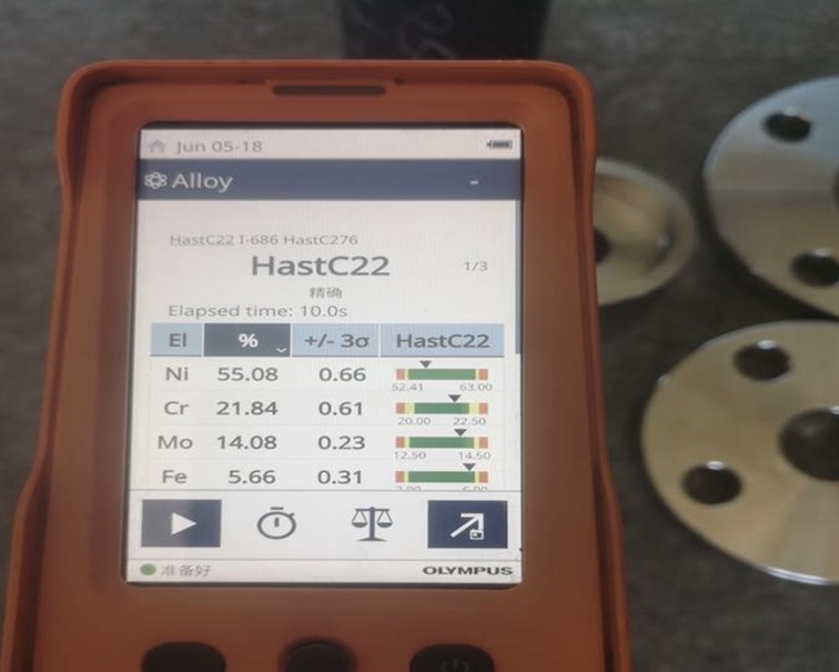
DIN 86029 Flange Materials
Commonly manufactured in:
- Carbon steel: e.g., C22.8, P235GH, S235JR
- Stainless steel: e.g., 1.4404 (316L), 1.4541 (321)
- Bronze / Copper alloys for seawater applications (in marine industry).
DIN 86029 Hubbed slipon flanges for welding: nominal pressure 10 .
DIN-86029-PN10-Hubbed-Slip-On-Flanges-for-Welding-Dimensions
measurements in mm
| Nominal size DN | pipe OD d1 | D | flange d5 b k h | neck d3 r | gasket width d4 | face height f | number | screws thread | d2 | weight (7.85 kg/dm3) kg | ||||
| For nominal sizes DN 10175 use DIN 86030 Nominal pressure 16 | ||||||||||||||
| 200 | 219,1 | 340 | 222 | 24 | 295 | 44 | 247 | 6 | 268 | 3 | 8 | M 20 | 22 | 9,9 |
| 250 | 273 | 395 | 276 | 26 | 350 | 46 | 300 | 6 | 320 | 3 | 12 | M 20 | 22 | 12,7 |
| 300 | 323,9 | 445 | 327 | 26 | 400 | 46 | 352 | 6 | 370 | 4 | 12 | M 20 | 22 | 14,4 |
| 350 | 355,6 | 505 | 359 | 26 | 460 | 53 | 398 | 10 | 430 | 4 | 16 | M20 | 22 | 22,3 |
| 400 | 406,4 | 565 | 410 | 26 | 515 | 57 | 448 | 10 | 482 | 4 | 16 | M24 | 26 | 26,7 |
| (450) | 457 | 615 | 461 | 28 | 565 | 62 | 502 | 10 | 532 | 4 | 20 | M24 | 26 | 32,3 |
| 500 | 508 | 670 | 512 | 28 | 620 | 67 | 552 | 10 | 585 | 4 | 20 | M24 | 26 | 37,3 |
| 600 | 610 | 780 | 614 | 28 | 725 | 75 | 658 | 10 | 685 | 5 | 20 | M27 | 30 | 48,3 |
| 700 | 711 | 895 | 716 | 30 | 840 | 77 | 760 | 10 | 800 | 5 | 24 | M27 | 30 | 62,7 |
| 800 | 813 | 1015 | 818 | 32 | 950 | 84 | 864 | 10 | 905 | 5 | 24 | M30 | 33 | 83,4 |
| 900 | 914 | 1115 | 920 | 34 | 1050 | 88 | 969 | 10 | 1005 | 5 | 28 | M30 | 33 | 99,2 |
| 1000 | 1016 | 1230 | 1022 | 34 | 1160 | 92 | 1071 | 10 | 1110 | 5 | 28 | M33 | 36 | 116,8 |
Do not use Nominal sizes in parentheses wherever possible.
Tolerances table 2
| Nominal size DN | D | d5 | b | k | h | d4 | d2 | d3 | r | f |
| 200 and 250 | ± 1 | ±2 | 0 2 | + 0,50 0 | DIN 7168g | |||||
| 300 | +1 | |||||||||
| 350 | ± 3 | 0 | ± 1,6 | |||||||
| 400 | ± 1,5 | ± 3 | 0 3 | +1 0 | ||||||
| 450 and 500 | + 1,5 | |||||||||
| 600 | ± 5 | 0 | ||||||||
| 700 to 1000 | +3 / 0 | DIN 7168g | ||||||||