As aprofessional manufacturer and exporter of EN 10253-4 Stainless Steel Tees, We are offering equal tees and reducing tees made from austenitic and duplex stainless steels. Our EN 10253-4 tees are designed for pressure piping systems, ensuring high corrosion resistance, durability, and leak-proof performance.
All fittings are produced according to EN 10253-4 Type A and Type B, fully tested, and supplied with EN 10204 3.1 certification.
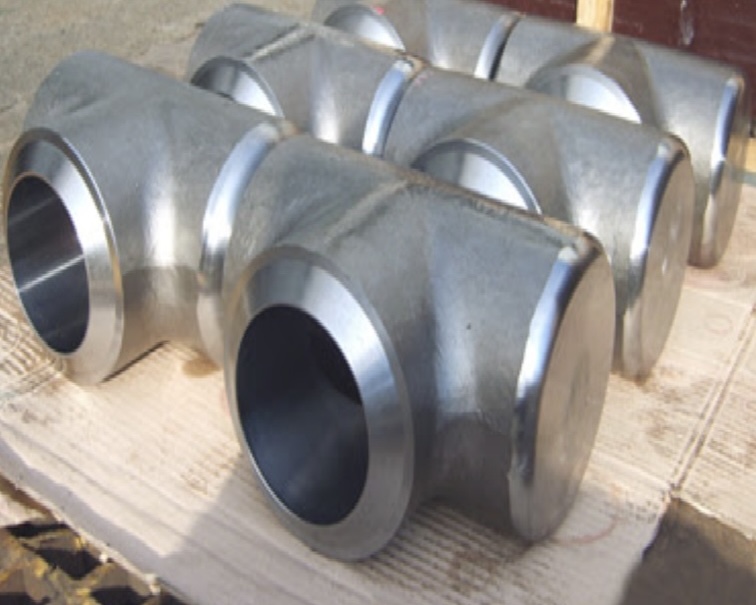
What is an EN 10253-4 Tee?
An EN 10253-4 Tee is a butt-weld pipe fitting used to combine or divide fluid flow in a pipeline.
The standard defines the technical delivery requirements for stainless steel butt-weld fittings including elbows, tees, reducers, and caps used in pressure pipelines and industrial installations.
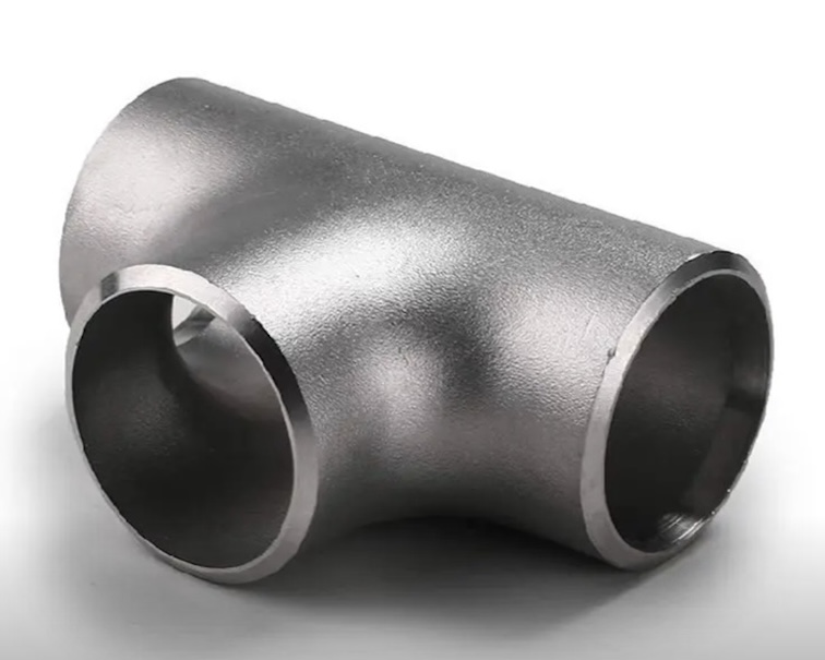
EN 10253-4 Tees are available in:
- Equal Tee (Straight Tee) — all three outlets are the same diameter
- Reducing Tee — branch outlet is smaller than the run pipes
Available Material Grades
| Material No. | Steel Grade | Equivalent ASTM / UNS | Type |
|---|---|---|---|
| 1.4301 | X5CrNi18-10 | AISI 304 / UNS S30400 | Austenitic |
| 1.4307 | X2CrNi18-9 | AISI 304L / UNS S30403 | Austenitic |
| 1.4404 | X2CrNiMo17-12-2 | AISI 316L / UNS S31603 | Austenitic |
| 1.4541 | X6CrNiTi18-10 | AISI 321 | Stabilized Austenitic |
| 1.4571 | X6CrNiMoTi17-12-2 | AISI 316Ti | Stabilized Austenitic |
| 1.4462 | X2CrNiMoN22-5-3 | Duplex UNS S31803 / S32205 | Duplex |
| 1.4410 | X2CrNiMoN25-7-4 | Super Duplex UNS S32750 | Super Duplex |
Heat Treatment
- Austenitic stainless steel tees: Solution annealed at 1050–1150°C, then water quenched.
- Duplex stainless steel tees: Solution annealed at 1020–1100°C, rapidly cooled.
Proper heat treatment ensures maximum corrosion resistance and ductility.
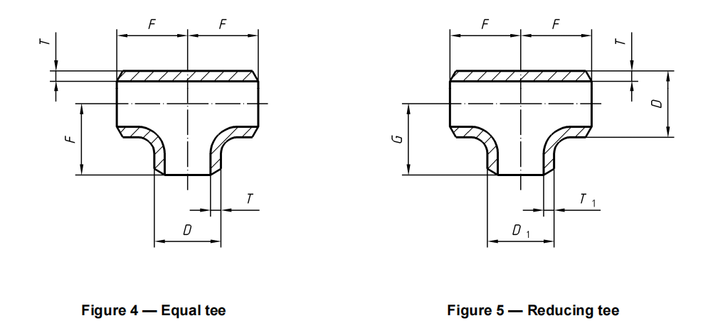
Table A.2 — Below is structural dimensions for tees, equal and reduced listed
| DN | Dmm | DN1 | D1mm | Fmm | Gmm | DN | Dmm | DN1 | D1mm | Fmm | Gmm |
| 15 | 21,3 | 15 | 21,3 | 25 | – | 300 | 323,9 | 300 | 323,9 | 254 | – |
| 20 | 26,9 | 20 | 26,9 | 29 | – | 250 | 273 | 241 | |||
| 15 | 21,3 | 29 | 200 | 219,1 | 229 | ||||||
| 25 | 33,7 | 25 | 33,7 | 38 | – | 150 | 168,3 | 219 | |||
| 20 | 26,9 | 38 | 350 | 355,6 | 350 | 355,6 | 279 | – | |||
| 15 | 21,3 | 38 | 300 | 323,9 | 270 | ||||||
| 32 | 42,4 | 32 | 42,4 | 48 | – | 250 | 273 | 257 | |||
| 25 | 33,7 | 48 | 200 | 219,1 | 248 | ||||||
| 20 | 26,9 | 48 | 400 | 406,4 | 400 | 406,4 | 305 | – | |||
| 15 | 21,3 | 48 | 350 | 355,6 | 305 | ||||||
| 40 | 48,3 | 40 | 48,3 | 57 | – | 300 | 323,9 | 295 | |||
| 32 | 42,4 | 57 | 250 | 273 | 283 | ||||||
| 25 | 33,7 | 57 | 450 | 457 | 450 | 457 | 343 | – | |||
| 20 | 26,9 | 57 | 400 | 406,4 | 330 | ||||||
| 50 | 60,3 | 50 | 60,3 | 64 | – | 350 | 355,6 | 330 | |||
| 40 | 48,3 | 60 | 300 | 323,9 | 321 | ||||||
| 32 | 42,4 | 57 | 500 | 508 | 500 | 508 | 381 | – | |||
| 25 | 33,7 | 51 | 450 | 457 | 368 | ||||||
| 65 | 76,1 | 65 | 76,1 | 76 | – | 400 | 406,4 | 356 | |||
| 50 | 60,3 | 70 | 350 | 355,6 | 356 | ||||||
| 40 | 48,3 | 67 | 600 | 610 | 600 | 610 | 432 | – | |||
| 32 | 42,4 | 64 | 500 | 508 | 432 | ||||||
| 80 | 88,9 | 80 | 88,9 | 86 | – | 450 | 457 | 419 | |||
| 65 | 76,1 | 83 | 400 | 406,4 | 406 | ||||||
| 50 | 60,3 | 76 | 700 | 711 | 700 | 711 | 521 | – | |||
| 40 | 48,3 | 73 | 800 | 813 | 800 | 813 | 597 | – | |||
| 100 | 114,3 | 100 | 114,3 | 105 | – | 900 | 914 | 900 | 914 | 673 | – |
| 80 | 88,9 | 98 | 1000 | 1016 | 1000 | 1016 | 749 | – | |||
| 65 | 76,1 | 95 | |||||||||
| 50 | 60,3 | 89 | |||||||||
| 125 | 139,7 | 125 | 139,7 | 124 | – | ||||||
| 100 | 114,3 | 117 | |||||||||
| 80 | 88,9 | 111 | |||||||||
| 65 | 76,1 | 108 | |||||||||
| 150 | 168,3 | 150 | 168,3 | 143 | – | ||||||
| 125 | 139,7 | 137 | |||||||||
| 100 | 114,3 | 130 | |||||||||
| 80 | 88,9 | 124 | |||||||||
| 200 | 219,1 | 200 | 219,1 | 178 | – | ||||||
| 150 | 168,3 | 168 | |||||||||
| 125 | 139,7 | 162 | |||||||||
| 100 | 114,3 | 156 | |||||||||
| 250 | 273 | 250 | 273 | 216 | – | ||||||
| 200 | 219,1 | 203 | |||||||||
| 150 | 168,3 | 194 | |||||||||
| 125 | 139,7 | 191 |
Table A.3 – Below are the structural dimensions for pulled tees, equal and reduced listed
| DN | Dmm | DN1 | D1mm | Fmm | hmm |
| 50 | 60,3 | 50 | 60,3 | 50 | 3 |
| 40 | 48,3 | 3 | |||
| 32 | 42,4 | 2 | |||
| 25 | 33,7 | 2 | |||
| 65 | 76,1 | 65 | 76,1 | 65 | 4 |
| 50 | 60,3 | 3 | |||
| 40 | 48,3 | 3 | |||
| 32 | 42,4 | 2 | |||
| 80 | 88,9 | 80 | 88,9 | 80 | 5 |
| 65 | 76,1 | 4 | |||
| 50 | 60,3 | 3 | |||
| 40 | 48,3 | 3 | |||
| 100 | 114,3 | 100 | 114,3 | 100 | 7 |
| 80 | 88,9 | 5 | |||
| 65 | 76,1 | 4 | |||
| 50 | 60,3 | 3 | |||
| 125 | 139,7 | 125 | 139,7 | 125 | 8 |
| 100 | 114,3 | 7 | |||
| 80 | 88,9 | 5 | |||
| 65 | 76,1 | 4 | |||
| 150 | 168,3 | 150 | 168,3 | 150 | 10 |
| 125 | 139,7 | 8 | |||
| 100 | 114,3 | 7 | |||
| 80 | 88,9 | 5 | |||
| 200 | 219,1 | 200 | 219,1 | 200 | 12 |
| 150 | 168,3 | 10 | |||
| 125 | 139,7 | 8 | |||
| 100 | 114,3 | 7 | |||
| 250 | 273 | 250 | 273 | 250 | 13 |
| 200 | 219,1 | 12 | |||
| 150 | 168,3 | 10 | |||
| 125 | 139,7 | 8 | |||
| 300 | 323,9 | 300 | 323,9 | 300 | 15 |
| 250 | 273 | 13 | |||
| 200 | 219,1 | 12 | |||
| 150 | 168,3 | 10 | |||
| 350 | 355,6 | 350 | 355,6 | 350 | 17 |
| 300 | 323,9 | 15 | |||
| 250 | 273 | 13 | |||
| 200 | 219,1 | 12 | |||
| 400 | 406,4 | 400 | 406,4 | 400 | 20 |
| 350 | 355,6 | 15 | |||
| 300 | 323,9 | 13 | |||
| 250 | 273 | 13 |
Table A.4 – Below are the structural dimensions for branch welded tees, equal and reduced listed
| DN | Dmm | DN1 | D1mm | Fmm | DN | Dmm | DN1 | D1mm | Fmm |
| 50 | 60,3 | 50 | 60,3 | 125 | 450 | 457 | 450 | 457 | 450 |
| 40 | 48,3 | 400 | 406,4 | ||||||
| 32 | 42,4 | 350 | 355,6 | ||||||
| 25 | 33,7 | 300 | 323,9 | ||||||
| 65 | 76,1 | 65 | 76,1 | 140 | 500 | 508 | 500 | 508 | 500 |
| 50 | 60,3 | 450 | 457 | ||||||
| 40 | 48,3 | 400 | 406,4 | ||||||
| 32 | 42,4 | 350 | 355,6 | ||||||
| 80 | 88,9 | 80 | 88,9 | 150 | 600 | 610 | 600 | 610 | 600 |
| 65 | 76,1 | 500 | 508 | ||||||
| 50 | 60,3 | 450 | 457 | ||||||
| 40 | 48,3 | 400 | 406,4 | ||||||
| 100 | 114,3 | 100 | 114,3 | 160 | 700 | 711 | 700 | 711 | 700 |
| 80 | 88,9 | 600 | 610 | ||||||
| 65 | 76,1 | 500 | 508 | ||||||
| 50 | 60,3 | 450 | 457 | ||||||
| 125 | 139,7 | 125 | 139,7 | 180 | 800 | 813 | 800 | 813 | 800 |
| 100 | 114,3 | 700 | 711 | ||||||
| 80 | 88,9 | 600 | 610 | ||||||
| 65 | 76,1 | 500 | 508 | ||||||
| 150 | 168,3 | 150 | 168,3 | 200 | 900 | 914 | 900 | 914 | 900 |
| 125 | 139,7 | 800 | 813 | ||||||
| 100 | 114,3 | 700 | 711 | ||||||
| 80 | 88,9 | 600 | 610 | ||||||
| 200 | 219,1 | 200 | 219,1 | 250 | 1000 | 1016 | 1000 | 1016 | 1000 |
| 150 | 168,3 | 900 | 914 | ||||||
| 125 | 139,7 | 800 | 813 | ||||||
| 100 | 114,3 | 700 | 711 | ||||||
| 250 | 273 | 250 | 273 | 300 | |||||
| 200 | 219,1 | ||||||||
| 150 | 168,3 | ||||||||
| 125 | 139,7 | ||||||||
| 300 | 323,9 | 300 | 323,9 | 330 | |||||
| 250 | 273 | ||||||||
| 200 | 219,1 | ||||||||
| 150 | 168,3 | ||||||||
| 350 | 355,6 | 350 | 355,6 | 360 | |||||
| 300 | 323,9 | ||||||||
| 250 | 273 | ||||||||
| 200 | 219,1 | ||||||||
| 400 | 406,4 | 400 | 406,4 | 400 | |||||
| 350 | 355,6 | ||||||||
| 300 | 323,9 | ||||||||
| 250 | 273 | ||||||||
Download EN 10253-4 Tee Dimension
Inspection and Testing
Each EN 10253-4 tee undergoes strict testing and inspection, including:
- Visual and dimensional inspection
- Hydrostatic or pneumatic pressure test
- Non-destructive testing (UT, PT, RT)
- Chemical composition verification
- Mechanical testing per EN ISO standards
- Certified to EN 10204 3.1 / 3.2
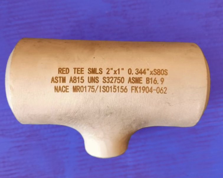
Marking and Documentation
Each tee is clearly marked with:
- Manufacturer’s logo or name
- Material grade and heat number
- Standard: EN 10253-4 Type A/B
- Size and wall thickness
- Batch number and inspection reference
Documentation includes full MTC (Material Test Certificate) and traceability data.
Example Order Information
Product: EN 10253-4 Tee
Type: Type B, Reducing Tee
Material: 1.4404 (X2CrNiMo17-12-2) – AISI 316L
Size: DN150 × DN100, SCH40
Manufacture: Seamless
Inspection: EN 10204 3.1
Related Products
- EN 10253-4 Elbow
- EN 10253-4 Reducer
- EN 10253-4 Cap
- EN 10253-2 Butt-Weld Fittings
- EN 1092-1 Flanges
- ASME B16.9 Pipe Tee