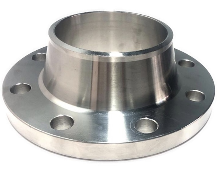
ASTM A105 Weld Neck Flange with SS316L Welding Overlay
We are a reliable manufacturer and supplier of ASTM A105 Carbon Steel Flanges with Weld Overlay (Clad Flanges).
These flanges combine the strength of carbon steel with the corrosion resistance of stainless steel or nickel alloys, making them ideal for oil, gas, and chemical processing industries.
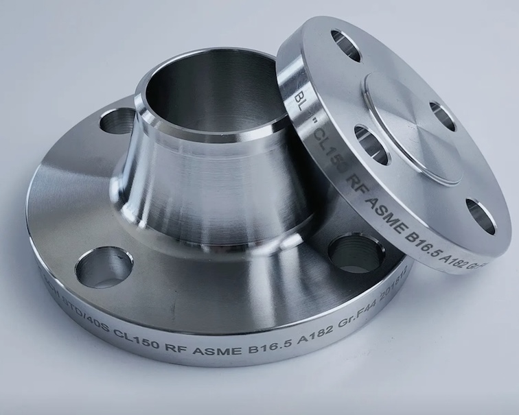
ASTM A105 weld neck flanges with ss 316L stainless steel welding overlay are specially engineered components combining carbon steel strength with corrosion-resistant stainless steel surfaces. These flanges are ideal for high-pressure, high-temperature, and corrosive environments such as oil & gas, chemical processing, refineries, and offshore industries.
A weld overlay flange is a flange made from a base material—typically carbon steel or low alloy steel—onto which a layer of corrosion-resistant alloy (CRA), such as stainless steel, Inconel, or Monel, is welded onto the sealing surface. This technique allows manufacturers to combine the mechanical strength of a cheaper base metal with the corrosion resistance of a high-performance alloy, achieving both cost efficiency and performance.
What Is a Weld Overlay Flange?
A weld overlay flange is produced by applying a layer of alloy material (such as SS316L, Inconel 625, Alloy 825, etc.) onto the wetted surfaces of a flange made from carbon steel like ASTM A105, A350 LF2, or A182 F11. This cladding is typically applied using GTAW (TIG), SMAW (stick), or SAW (submerged arc welding) methods.
ASTM A105 316L Welding overlay flanges specification
- Base Material: ASTM A105/A105N (Carbon Steel, forged)
- Overlay Material: SS316L (Low-Carbon Austenitic Stainless Steel)
- Flange Type: Weld Neck (WN)
- Face:Ring joint or raise face
- Standards: ASME B16.5 / ASME B16.47 / MSS-SP-44
- Pressure Ratings: Class 150 – 2500
- Size Range: ½” – 48” (DN15 – DN1200)
Why Use SS316L Overlay on A105?
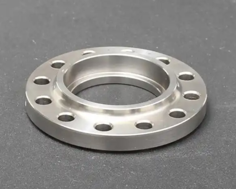
The welding overlay (cladding) of SS316L on the wetted surface of the A105 flange enhances its resistance to corrosion, pitting, and crevice attack from chemicals, seawater, acids, and chlorides — while the A105 core provides excellent mechanical strength and cost efficiency.
316L Stainless Steel Features:
- Low carbon = better weldability and intergranular corrosion resistance
- Resistant to chloride corrosion and acidic environments
- Excellent durability in aggressive media (acetic, sulfuric acids)
A105 316L Welding overlay flanges Manufacturing Process
- Flange Forging (A105)
- Machining of base shape
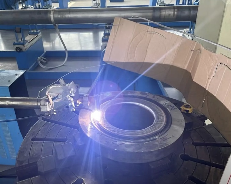
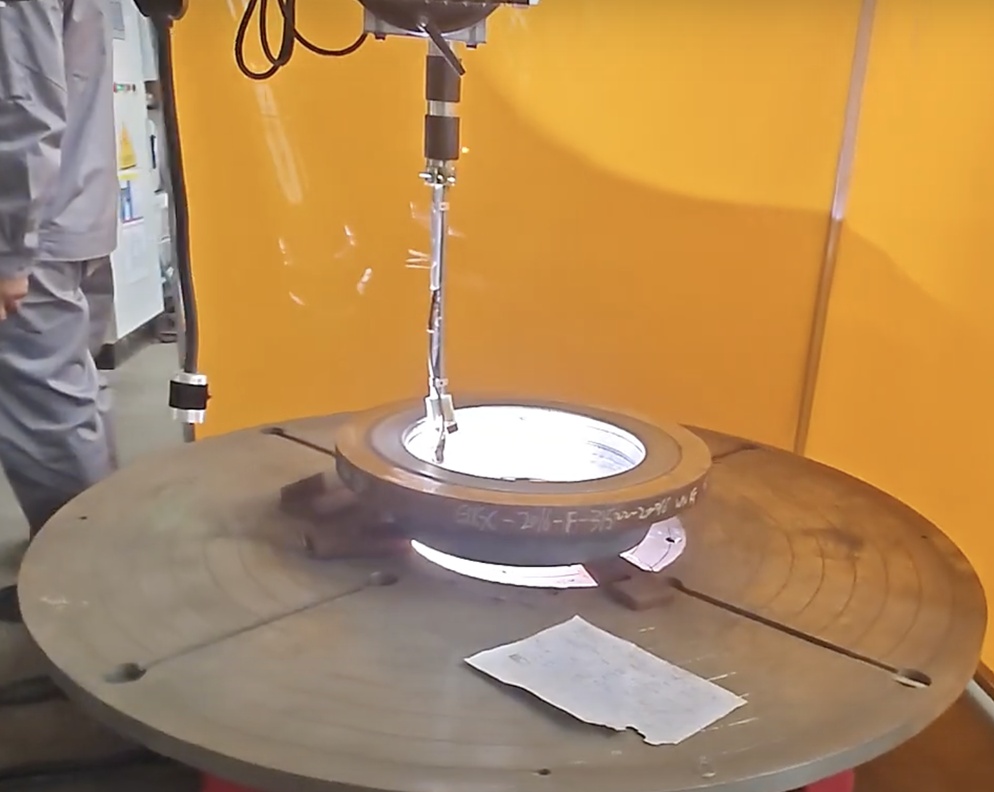
- Welding Overlay (cladding) using GTAW/SMAW/SAW process with SS316L filler metal
- Post-weld Heat Treatment (if required)
- Final machining to dimensions (ASME/DIN/JIS)
- Inspection & Testing (Visual, PMI, UT, Hardness)
A105 316L Welding overlay flanges Specifications Summary
| Parameter | Value |
|---|---|
| Flange Material | ASTM A105 (Forged Carbon Steel) |
| Cladding Material | SS316L (UNS S31603) |
| Overlay Thickness | Typically 3mm – 5mm thickness overlay |
| Standards | ASME B16.5 / B16.47 / MSS-SP-44 |
| Testing | PMI, UT, PT, Hydro, Dimensional |
| Documentation | EN 10204 3.1 / 3.2 MTC, NACE MR0175 |
| Application Standard | NORSOK, Shell DEP, Total GS, Aramco |
Welding overlay flanges Applications
- Offshore oil platforms & FPSOs
- Sour gas (H₂S) systems (NACE MR0175)
- Petrochemical and refinery piping
- Desalination and seawater cooling lines
- Chemical reactors and pressure vessels
Common flange body and Cladding material
| Base Material | Cladding Material | Application Example |
|---|---|---|
| ASTM A105 | SS316L | Oil & gas, seawater lines |
| ASTM A182 F11 | Inconel 625 | Sour service (H₂S), offshore |
| ASTM A350 LF2 | Alloy 825 | Chemical processing |
| ASTM A516 Gr.70 | SS317L | Desalination, pulp & paper |
Weld Overlay Flange Manufacturer & Exporter
As a leading manufacturer of weld overlay flanges, we offer:
- In-house overlay welding (GTAW, SAW, etc.)
- Full NDT and material traceability
- Short delivery times with global export packing
Cladding Flange Manufacturing Process Flow
I. Pre-Production Preparation
- Base Flange Preparation
- Material Selection: Carbon steel (e.g., SA350 LF2, A105) or low-alloy steel (e.g., SA182 F11/F22).
- Blank Machining:
- Cut/forge ring blanks from round bars or plates.
- Rough-machine overall dimensions (OD, ID, thickness, bolt hole circle).
- Allow 3–5+ mm machining allowance on cladding surfaces.
- Groove Preparation:
- Machine grooves on sealing faces:
- Flat Surface: Simple but high dilution.
- Recessed Groove (U/Rectangular): Preferred for lower dilution.
- Machine grooves on sealing faces:
- Cleaning: Degrease + mechanically grind (stainless brush) to bare metal.
- Cladding Material Prep
- Material: Austenitic SS (ER308L/309L/316L), Ni-alloy (ERNiCrMo-3), or Co-alloy (Stellite 6).
- Form: Wire (MIG/TIG/SAW), Strip (SAW/ESW), or Electrode (SMAW).
- Preheat: Dry electrodes per AWS/EN standards.
- Equipment Setup
- Rotator/turning rolls for uniform deposition.
- Welding power source (SAW/GTAW/GMAW/SMAW).
- Preheating tools (if required per WPS).
- Temperature guns, fume extraction.
II. Welding Procedure Qualification (WPQ)
- WPS Qualification: Qualify per ASME Sec. IX or ISO 15614.
- Essential Variables:
- Base/clad material grades.
- Preheat/interpass temp.
- Heat input (kJ/mm).
- Number of layers.
III. Cladding Process
- Preheating (If Applicable)
- Preheat base to 100–200°C (material-dependent).
- Monitor with temp sticks/IR gun.
- Buttering Layer (Critical for dissimilar metals)
- Deposit 1–2 transition layers (e.g., ER309L on carbon steel).
- Control dilution < 10%.
- Cladding Layer Deposition
- Process Selection:MethodApplicationSAW (Strip)High-speed, flat surfacesGTAW (Wire)Precision, complex geometriesSMAWRepairs/small batches
- Key Controls:
- Interpass temp ≤ 150°C (SS/Ni-alloys).
- Layer thickness: 3–4 mm/layer.
- Overlap: 30–50% for strip cladding.
- Post-Weld Cooling
- Slow cooling (cover with thermal blanket) for crack-sensitive alloys.
IV. Post-Cladding Treatment
- Stress Relief (If Required)
- PWHT per base material code (e.g., ASME B31.3).
- Caution: Avoid sensitization of SS (e.g., 870°C max for 316L).
- Machining
- Finish-machine sealing face to Ra ≤ 3.2 μm.
- Verify clad thickness ≥ design min. (e.g., 3 mm).
V. Inspection & Testing
- NDE:
- VT: Per ASME B31.3 – no cracks, undercut.
- PT/MT: Surface defects on clad/base.
- UT: Bond integrity (interface defects).
- Destructive Testing (Sample Coupons):
- Hardness survey (clad, HAZ, base).
- Chemical analysis (PMI) of clad layer.
- Corrosion test (ASTM G48/A262).
VI. Documentation
- MTRs for base/clad materials.
- WPS/PQR records.
- NDE reports (PT/UT/RT).
- Final dimensional report.
Example Order Information
Product: ASTM A105 + SS316L Weld Neck Flange
Size: 12” Class 600 RF
Standard: ASME B16.5
Overlay Thickness: 3 mm
Welding Process: GTAW + SAW
Testing: UT + PT + Chemical Analysis
Certification: EN 10204 3.1 + NACE MR0175
Related Products
- ASTM A105 Carbon Steel Flanges
- ASTM A350 LF2 Low-Temperature Flanges
- ASTM A694 F65 High-Strength Flanges
- Inconel 625 Weld Overlay Flanges