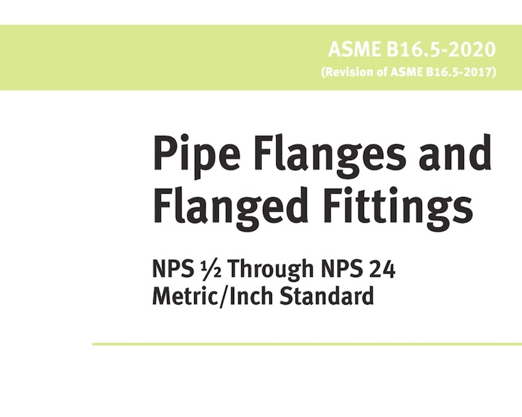
ASME B16.5 2020
ASME B16.5 covers pipe flanges and flanged fittings for sizes NPS ½ through 24 and pressure classes 150 through 2500. It defines dimensions, tolerances, materials, marking, and testing requirements.
ASME B16.5 standard is one of the most important code for Flange and flanged fittings designing,manuafacturing and installation in the pipeline industries . Here we would like to introduce the ASME B16.5 standards histories and the main content in the latest edition ASME B16.5 2020.also you can download the ASME B16.5 2020 standard in PDF.
ASME B16.5 Edition History
| Edition Year | Key Notes / Changes |
|---|---|
| 1927 (ASA B16e) | First edition published by the American Standards Association (ASA), under the B16 committee. |
| 1932 / 1939 / 1949 | Revisions updated material specifications and dimensions. |
| 1955 | Renamed to ASA B16.5-1955, focused on cast iron and steel flanges. |
| 1968 | Adopted by ANSI (American National Standards Institute); improved format. |
| 1973 | ANSI B16.5-1973 – Introduced more refined pressure-temperature ratings. |
| 1977 | Included welding neck and slip-on flanges; enhanced material specs. |
| 1981 | First edition under ASME (not ANSI/ASA); improved clarity and metrication. |
| 1988 | Incorporated metric dimensions alongside U.S. customary units. |
| 1996 | Major reorganization of content for better clarity and use. |
| 2003 | Introduced Appendix E for bolting, gasket, and flange assembly guidelines. |
| 2009 | Expanded guidance on facing finish and tolerances. Improved compatibility with international standards. |
| 2013 | Editorial and dimensional refinements; included more references to MSS and ASTM specs. |
| ASME B16.5 2017 | Clarified flange facings and tolerances; improved marking requirements. |
| ASME B16.5 2020 | Major changes: integrated U.S. Customary units into the main text, revised flange thickness nomenclature, added straight hub welding flanges. Appendix II was deleted. |
List of Material Specification for ASME B16.5 Flanges
Material for flanges and flanged fittings may meet the requirements of more than one specification or the requirements of more than one grade of a specification listed below
(1) Plate and flat bar materials may be used only for blind flanges and reducing flanges without hubs.
(2) Flanges and flanged fittings shall be manufactured as one piece in accordance with the applicable material specification.
| Group 1 Materials – 1.1 | C – Si | 2 – 1.1 | A105 | A216 Gr. WCB | A515 Gr. 70 |
| C – Mn – Si | 2 – 1.1 | A350 Gr. LF2 | – | A516 Gr. 70 | |
| C – Mn – Si | 2 – 1.1 | – | – | A537 Cl. 1 | |
| C – Mn – Si – V | 2 – 1.1 | A350 Gr. LF6 Cl. 1 | – | – | |
| 3 1/2Ni | 2 – 1.1 | A350 Gr. LF3 | – | – | |
| Group 1 Materials – 1.2 | C – Mn – Si | 2 – 1.2 | – | A216 Gr. WCC | – |
| C – Mn – Si | 2 – 1.2 | A350 Gr. LF6 Cl. 2 | A352 Gr. LCC | – | |
| 2 1/4Ni | 2 – 1.2 | – | A352 Gr. LC2 | A203 Gr. B | |
| 3 1/2Ni | 2 – 1.2 | – | A352 Gr. LC3 | A203 Gr. E | |
| Group 1 Materials – 1.3 | C – Si | 2 – 1.3 | – | A352 Gr. LCB | A515 Gr. 65 |
| C – Mn – Si | 2 – 1.3 | – | – | A516 Gr. 65 | |
| 2 1/2Ni | 2 – 1.3 | – | – | A203 Gr. A | |
| 3 1/2Ni | 2 – 1.3 | – | – | A203 Gr. D | |
| C – 1/2Mo | 2 – 1.3 | – | A217 Gr. WC1 | – | |
| C – 1/2Mo | 2 – 1.3 | – | A352 Gr. LC1 | – | |
| Group 1 Materials – 1.4 | C – Si | 2 – 1.4 | – | – | A515 Gr. 60 |
| C – Mn – Si | 2 – 1.4 | A350 Gr. LF1 Cl. 1 | – | A516 Gr. 60 | |
| Group 1 Materials – 1.5 | C – 1/2Mo | 2 – 1.5 | A182 Gr. F1 | – | A204 Gr. A |
| Group 1 Materials – 1.7 | C – 1/2Mo | 2 – 1.7 | A182 Gr. F2 | – | A200 Gr. B |
| 1/2Ni – 1/2Cr – 1/2Mo | 2 – 1.7 | – | A217 Gr. WC4 | – | |
| 3/4Ni – 1/2Cr – 1/2Mo | 2 – 1.7 | – | A217 Gr. WC5 | – | |
| Group 1 Materials – 1.9 | 1 1/4Ni – 1/2Cr – 1/2Mo | 2 – 1.9 | A182 Gr. F11 Cl. 2 | – | A387 Gr. 11 Cl. 2 |
| 1 1/4Ni – 1/2Cr – 1/2Mo – Si | 2 – 1.10 | A182 Gr. F22 Cl. 3 | A217 Gr. WC9 | A387 Gr. 22 Cl. 2 | |
| Group 1 Materials – 1.11 | C – 1/2Mo | 2 – 1.11 | – | – | A204 Gr. C |
| 1 1/4Cr – 1/2Mo | 2 – 1.13 | A182 Gr. F5a | A217 Gr. C5 | – | |
| Group 1 Materials – 1.14 | 9Cr – 1Mo | 2 – 1.14 | A182 Gr. F9 | A217 Gr. C12 | – |
| Group 1 Materials – 1.15 | 9Cr – 1Mo – V | 2 – 1.15 | A182 Gr. F91 Type 1 | A217 Gr. C12A | A387 Gr. 91 Cl. 2 |
| Group 1 Materials – 1.17 | 1 1/4Cr – 1/2Mo | 2 – 1.17 | A182 Gr. F12 Cl. 2 | – | – |
| 5Cr – 1/2Mo | 2 – 1.17 | A182 Gr. F5 | – | – | |
| Group 1 Materials – 1.18 | 9Cr – 2W – V | 2 – 1.18 | A182 Gr. F92 | – | – |
| Group 2 Materials – 2.1 | 18Cr – 8Ni | 2 – 2.1 | A182 Gr. F304 | A351 Gr. CF3 | A240 Gr. 304 |
| 18Cr – 8Ni | 2 – 2.1 | A182 Gr. F304H | A351 Gr. CF8 | A240 Gr. 304H | |
| 16Cr – 12Ni – 2Mo | 2 – 2.2 | A182 Gr. F316 | A351 Gr. CF3M | A240 Gr. 316 | |
| 16Cr – 12Ni – 2Mo | 2 – 2.2 | A182 Gr. F316H | A351 Gr. CF8M | A240 Gr. 316H | |
| 18Cr – 13Ni – 3Mo | 2 – 2.2 | A182 Gr. F317 | A351 Gr. CGBM | A240 Gr. 317 | |
| 19Cr – 10Ni – 3Mo | 2 – 2.2 | – | – | – | |
| Group 2 Materials – 2.3 | 18Cr – 8Ni | 2 – 2.3 | A182 Gr. F304L | – | A240 Gr. 304L |
| 16Cr – 12Ni – 2Mo | 2 – 2.3 | A182 Gr. F316L | – | A240 Gr. 316L | |
| 18Cr – 13Ni – 3Mo | 2 – 2.3 | A182 Gr. F317L | – | – | |
| Group 2 Materials – 2.4 | 18Cr – 10Ni – Ti | 2 – 2.4 | A182 Gr. F321 | – | A240 Gr. 321 |
| 18Cr – 10Ni – Ti | 2 – 2.4 | A182 Gr. F321H | – | A240 Gr. 321H | |
| Group 2 Materials – 2.5 | 18Cr – 10Ni – Cb | 2 – 2.5 | A182 Gr. F347 | – | A240 Gr. 347 |
| 18Cr – 10Ni – Cb | 2 – 2.5 | A182 Gr. F347H | – | A240 Gr. 347H | |
| 18Cr – 10Ni – Cb | 2 – 2.5 | A182 Gr. F348 | – | A240 Gr. 348 | |
| 18Cr – 10Ni – Cb | 2 – 2.5 | A182 Gr. F348H | – | A240 Gr. 348H | |
| Group 2 Materials – 2.6 | 23Cr – 12Ni | 2 – 2.6 | – | – | A240 Gr. 309 |
| Group 2 Materials – 2.7 | 25Cr – 20Ni | 2 – 2.7 | A182 Gr. F310 | – | A240 Gr. 310H |
| Group 2 Materials – 2.8 | 20Cr – 18Ni – 6Mo | 2 – 2.8 | A182 Gr. F44 | – | A240 Gr. S31254 |
| 22Cr – 5Ni – 3Mo – N | 2 – 2.8 | A182 Gr. F51 | A351 Gr. CK3MCuN | A240 Gr. S31803 | |
| 25Cr – 7Ni – 4Mo – N | 2 – 2.8 | A182 Gr. F53 | – | A240 Gr. S32750 | |
| 24Cr – 10Ni – 4Mo – V | 2 – 2.8 | – | – | – | |
| 25Cr – 5Ni – 2Mo – 3Cu – N | 2 – 2.8 | – | A995 Gr. CD4MCuN | – | |
| 25Cr – 7Ni – 3.5Mo – W – Cu | 2 – 2.8 | – | A995 Gr. CD3MWCuN | – | |
| 25Cr – 7.5Ni – 3.5Mo – N – Cu – W | 2 – 2.8 | A182 Gr. F55 | – | A240 Gr. S32760 | |
| Group 2 Materials – 2.9 | 23Cr – 12Ni | 2 – 2.9 | – | – | A240 Gr. 309S |
| 25Cr – 12Ni | 2 – 2.9 | – | – | A240 Gr. 310S | |
| Group 2 Materials – 2.10 | 25Cr – 12Ni | 2 – 2.10 | – | A351 Gr. CH8 | – |
| 25Cr – 12Ni | 2 – 2.10 | – | A351 Gr. CH20 | – | |
| Group 2 Materials – 2.11 | 18Cr – 20Ni – Cb | 2 – 2.11 | – | A351 Gr. CF8C | – |
| Group 2 Materials – 2.12 | 25Cr – 20Ni | 2 – 2.12 | – | A351 Gr. CK20 | – |
| Group 3 Materials – 3.1 | 35Ni – 35Fe – 20Cr – Cb | 2 – 3.1 | A182 Gr. N08020 | – | A182 Gr. N08020 Flange |
| Group 3 Materials – 3.2 | 99Ni | 2 – 3.2 | – | – | B162 Gr. N02200 |
| Group 3 Materials – 3.3 | 99Ni – Low C | 2 – 3.3 | – | – | B162 Gr. N02201 |
| Group 3 Materials – 3.4 | 67Ni – 30Cu | 2 – 3.4 | B564 Gr. N04400 | – | B127 Gr. N04400 |
| Group 3 Materials – 3.5 | 72Ni – 15Cr – 8Fe | 2 – 3.5 | B564 Gr. N06600 | – | B168 Gr. N06600 |
| Group 3 Materials – 3.6 | 33Ni – 42Fe – 21Cr | 2 – 3.6 | A182 Gr. N08800 | – | A182 Gr. N08800 |
| 65Ni – 28Mo – 2Fe | 2 – 3.7 | B462 Gr. N10665 | – | B333 Gr. N10665 | |
| Group 3 Materials – 3.7 | 64Ni – 29Mo – 2Cr – 2Fe – Mn – W | 2 – 3.7 | B462 Gr. N10675 | – | B333 Gr. N10675 |
| 54Ni – 16Mo – 15Cr | 2 – 3.8 | B462 Gr. N06276 | – | B575 Gr. N06276 | |
| 60Ni – 22Cr – 9Mo – 3.5Cb | 2 – 3.8 | B564 Gr. N06625 | – | B443 Gr. N06625 | |
| 62Ni – 28Mo – 5Fe | 2 – 3.8 | – | – | B333 Gr. N10001 | |
| 70Ni – 16Mo – 7Cr – 5Fe | 2 – 3.8 | – | – | B434 Gr. N10003 | |
| 61Ni – 16Mo – 16Cr | 2 – 3.8 | B564 Gr. N08825 | – | B575 Gr. N06455 | |
| 42Ni – 21Cr – 3Mo – 2.3Cu | 2 – 3.8 | B462 Gr. N06022 | – | B424 Gr. N08825 | |
| 55Ni – 21Cr – 13.5Mo | 2 – 3.8 | – | – | B575 Gr. N06022 | |
| 55Ni – 23Cr – 16Mo – 1.6Cu | 2 – 3.8 | B462 Gr. N06200 | – | B575 Gr. N06200 | |
| Group 3 Materials – 3.9 | 47Ni – 22Cr – 9Mo – 18Fe | 2 – 3.9 | B572 Gr. N06002 | – | B435 Gr. N06002 |
| 31Ni – 30Fe – 22Cr – 18Mo – 3 – 3W | 2 – 3.9 | B572 Gr. R30556 | – | B435 Gr. R30556 | |
| Group 3 Materials – 3.10 | 25Ni – 47Fe – 21Cr – 5Mo | 2 – 3.10 | – | – | B599 Gr. N08700 |
| Group 3 Materials – 3.11 | 44Fe – 25Ni – 21Cr – Mo | 2 – 3.11 | A182 Gr. N08904 | – | A240 Gr. N08904 |
| 26Ni – 43Fe – 22Cr – 5Mo | 2 – 3.12 | – | – | B620 Gr. N08320 | |
| Group 3 Materials – 3.12 | 47Ni – 22Cr – 20Fe – 7Mo | 2 – 3.12 | – | – | B582 Gr. N06985 |
| 46Fe – 24Ni – 21Cr – 6Mo – Cu – N | 2 – 3.12 | A182 Gr. N08367 | A351 Gr. CN3MN | A688 Gr. N08367 | |
| 46Fe – 24Ni – 21Cr – 6Mo – Cu – N | 2 – 3.12 | B462 Gr. N08367 | A351 Gr. CN3MN | A688 Gr. N08367 |
Bolting material for ASME B16.5 Flanges
Bolting listed in Table 1.1-2 is recommended for use in flanged joints covered by this Standard. Bolting of other material may be used if permitted by theapplicable code or government regulation.
| High Strength | Intermediate Strength (3) | Low Strength (4) | Nickel and Special Alloy (5) | ||||||||
| Spec. No. | Grade | Notes | Spec. No. | Grade | Notes | Spec. No. | Grade | Notes | Spec. No. | Grade | Notes |
| A193 | B7 | … | A193 | B5 | … | A193 | B8 Cl. 1 | -6 | B164 | … | (7)-(9) |
| A193 | B16 | … | A193 | B6 | … | A193 | B8C Cl. 1 | -6 | … | … | … |
| … | A193 | B6X | … | A193 | B8M Cl. 1 | -6 | B166 | … | (7)-(9) | ||
| A320 | L7 | -10 | A193 | B7M | … | A193 | B8T Cl. 1 | -6 | … | … | … |
| A320 | L7A | -10 | |||||||||
| A320 | L7B | -10 | A193 | B8 Cl. 2 | -11 | A193 | B8A | -6 | B335 | N10665 | -7 |
| N10675 | -7 | ||||||||||
| A320 | L7C | -10 | A193 | B8 Cl. 2B | -11 | ||||||
| A320 | L43 | -10 | A193 | B8C Cl. 2 | -11 | A193 | B8CA | … | |||
| A193 | B8M Cl. 2 | -11 | A193 | B8MA | … | B408 | … | (7)-(9) | |||
| A193 | B8M Cl. 2B | -11 | |||||||||
| A193 | B8T Cl. 2 | -11 | A193 | B8TA | -6 | ||||||
| A354 | BC | … | B473 | … | -7 | ||||||
| A354 | BD | … | A320 | B8 Cl. 2 | -11 | A307 | B | -12 | |||
| A320 | B8C Cl. 2 | -11 | B574 | … | -7 | ||||||
| A540 | B21 | … | A320 | B8F Cl. 2 | -11 | A320 | B8 Cl. 1 | -6 | |||
| A540 | B22 | … | A320 | B8M Cl. 2 | -11 | A320 | B8C Cl. 1 | -6 | |||
| A540 | B23 | … | A320 | B8T Cl. 2 | -11 | A320 | B8M Cl. 1 | -6 | |||
| A540 | B24 | … | A320 | B8T Cl. 1 | -6 | ||||||
| A449 | -13 | ||||||||||
| A453 | 651 | -14 | |||||||||
| A453 | 660 | -14 | |||||||||
Flange Bolting Dimensional Recommendations
Dimensional Standards. Stud bolts, threaded at both ends or threaded full length, or bolts may be used in flange joints. Dimensional recommended as below
| Product | Carbon Steel | Alloy Steel |
|---|---|---|
| Stud bolts | ASME B18.31.2 | ASME B18.31.2 |
| Bolts smaller than ¾ in. | ASME B18.2.1, square or heavy hex head | ASME B18.2.1, heavy hex head |
| Bolts equal to or larger than ¾ in. | ASME B18.2.1, square or heavy hex head | ASME B18.2.1, heavy hex head |
| Nuts smaller than ¾ in. | ASME B18.2.2, heavy hex | ASME B18.2.2, heavy hex |
| Nuts equal to or larger than ¾ in. | ASME B18.2.2, hex or heavy hex | ASME B18.2.2, heavy hex |
Gasket for ASME B16.5 Flanges
Ring joint gasket materials shall conform to ASME B16.20. Materials for other gaskets are described in Nonmandatory Appendix B. The user is responsible for selection of gasket materials that will withstand the expected bolt loading without injurious crushing and that are suitable for the service conditions. Particular attention should be given to gasket selection if a system hydrostatic test approache
ASME B16.5 DIMENSIONS
ASME B16.5 provides standardized dimensions for pipe flanges and flanged fittings, covering sizes from NPS ½ to 24 inches and pressure classes 150 through 2500.
ASME B16.5 specifies dimensions for various flange types, including:
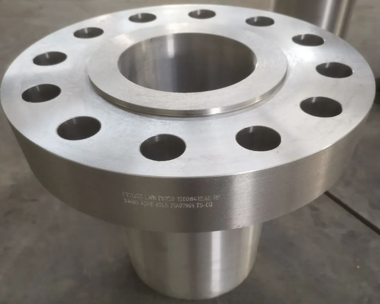
- Weld Neck (WN)
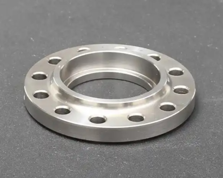
- Slip-On (SO)
- Blind (BL)
- Socket Weld (SW)
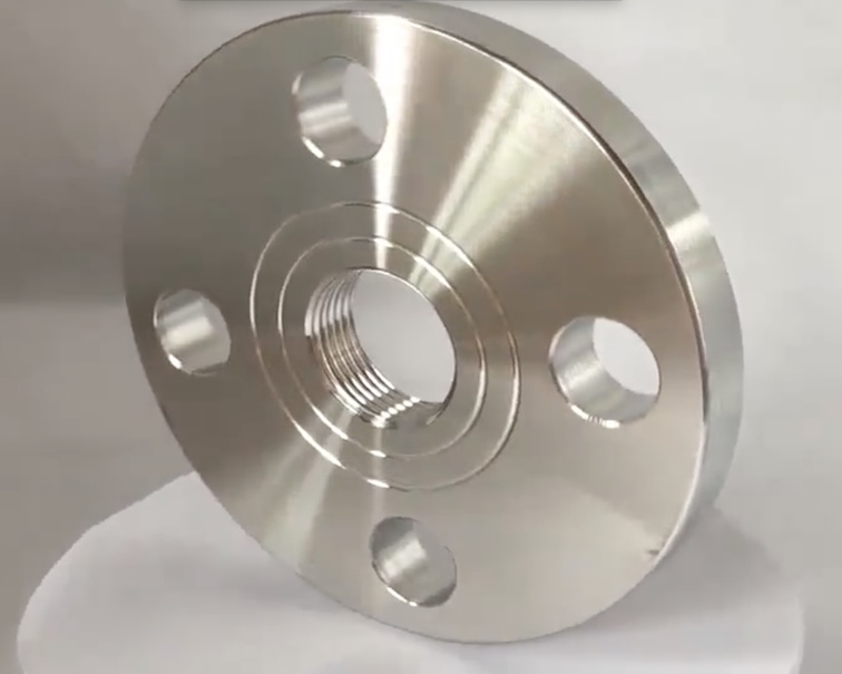
- Threaded (TH)
- Lap Joint (LJ)
You can Check and download the ASME B16.5 DIMENSIONS Table here.
ASME B16.5 2020 CL150 Flange Dimension
ASME B16.5 2020 CL300 Flange Dimension
ASME B16.5 2020 CL400 Flange Dimension
ASME B16.5 2020 CL600 Flange Dimension
ASME B16.5 2020 CL900 Flange Dimension
ASME B16.5 2020 CL1500 Flange Dimension
ASME B16.5 2020 CL2500 Flange Dimension
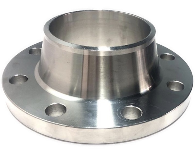
ASME B16.5 Weld Neck Flanges
Welded neck flanges
Also known as Butt weld flanges. Their long necks are butt welded to a pipe. The flange’s bore matches that of the pipe, reducing turbulence and erosion. This flanged connection relocates stress to the pipes, ensuring a decrease in high-stress concentration at the bottom of the flange. When installing, weld neck pipe flanges must be positioned parallel at the time of fitting. Flanges at opposite ends of a pipe should typically have the same bolt-hole direction too.
Download the Dimension of ASME B16.5 Weld neck Flange
⬇️ Download Dimension of Weld Neck flanges Class 150 lbs ASME B16.5 PDF
⬇️ Download Dimension of Weld Neck flanges Class 300 lbs ASME B16.5 PDF
⬇️ Download Dimension of Weld Neck flanges Class 400 lbs ASME B16.5 PDF
⬇️ Download Dimension of Weld Neck flanges Class 600 lbs ASME B16.5 PDF
⬇️ Download Dimension of Weld Neck flanges Class 900 lbs ASME B16.5 PDF
⬇️ Download Dimension of Weld Neck flanges Class 1500 lbs ASME B16.5 PDF
⬇️ Download Dimension of Weld Neck flanges Class 2500 lbs ASME B16.5 PDF
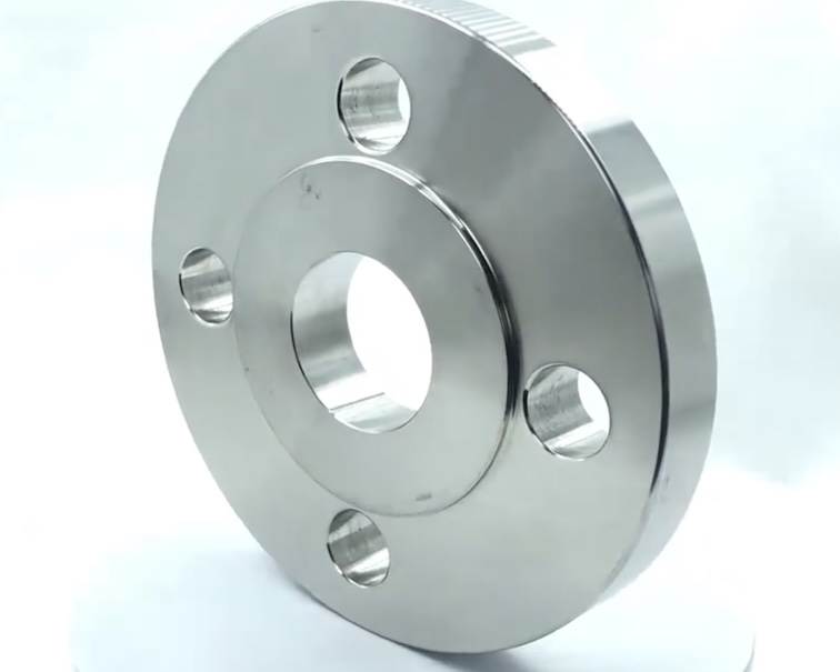
ASME B16.5 Slip-on flanges
These low-pressure flanges are thinner than most other flanges. With an inside diameter slightly larger than the pipe’s outside diameter, the flange slips onto the pipe. A fillet weld is applied at the top of the flange and at the bottom. The welds enhance strength and prevent leakage. Also known as hubbed flanges. Installation of slip-on pipe flanges is easy and therefore low cost.
Download the Dimension of ASME B16.5 Slip on Flange
⬇️ Download Dimension of Slip on flanges Class 150 lbs ASME B16.5 PDF
⬇️ Download Dimension of ASME B16.5 Class 300 lbs Slip on flanges PDF
⬇️ Download Dimension of ASME B16.5 Class 400 lbs Slip on flanges PDF
⬇️ Download Dimension of ASME B16.5 Class 600 lbs Slip on flanges PDF
⬇️ Download Dimension of ASME B16.5 Class 900 lbs Slip on flanges PDF
⬇️ Download Dimension of ASME B16.5 Class 1500 lbs Slip on flanges PDF
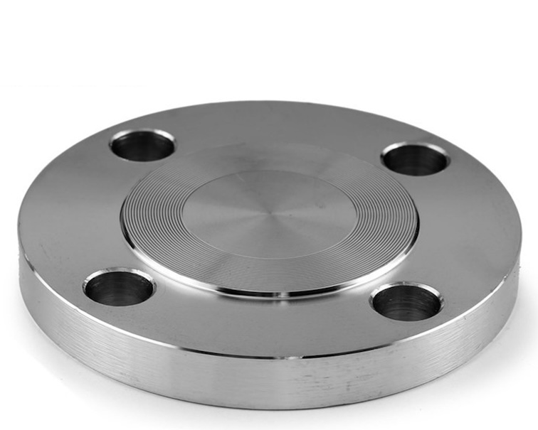
ASME B16.5 Blind flanges
The lack of an inner hole enables blind flanges to seal off the end of pipe systems, preventing flow. This makes it easier and more cost efficient to carry out pressure tests. The blind flange connection is also an ideal pipeline flange. You can stop the flow of fluid and safely add new pipes or new lines to the pipeline.
Without blind flanges, shutdowns and repairs would be incredibly difficult to handle. While shutoff valves solve the problem of stopping flow, the location of the valve can be a problem. For example, if the valves are a mile or two away, then you’re looking at a significant amount of wasted fluid.
Download the Dimension of ASME B16.5 Blind Flange
⬇️ Download Dimension of Blind Flange ASME B16.5 Class 150 lbs PDF
⬇️ Download Dimension of Blind Flange ASME B16.5 Class 300 lbs PDF
⬇️ Download Dimension of Blind Flange ASME B16.5 Class 400 lbs PDF
⬇️ Download Dimension of Blind Flange ASME B16.5 Class 600 lbs PDF
⬇️ Download Dimension of Blind Flange ASME B16.5 Class 900 lbs PDF
⬇️ Download Dimension of Blind Flange ASME B16.5 Class 1500 lbs PDF
⬇️ Download Dimension of Blind Flange ASME B16.5 Class 2500 lbs PDF
ASME B16.5 Dimension tolerance
WELDING NECK FLANGES Tolerance
| O | Outside Diameter | When 0 is 24″ or less | ±0.06″ | ±1.6 mm |
| When O is over 24” | ±0.12″ | ±3.2 mm | ||
| R | Diameter of Contact Face | 0.06” (1.6 mm) raised face | ±0.03″ | ±0.8 mm |
| 0.25″ (6.4 mm) raised face | ±0.02″ | ±0.5 mm | ||
| A | Diameter of Hub at Point of Welding | NPS 5 and smaller | +0.09″, -0.03″ | +2.4 mm, -0.8 mm |
| NPS 6 and larger | +0.16″, -0.03″ | +4.0 mm, -0.8 mm | ||
| B | Inside Diameter | NPS 10 and smaller | ±0.03″ | ±0.8 mm |
| NPS 12 to 18, inclusive | ±0.06″ | ±1.6 mm | ||
| NPS 20 and larger | +0.12″, -0.06” | +3.2 mm, -1.6 mm | ||
| X | Diameter of Hub at Base | When Hub Base is 24″ or less | ±0.06″ | ±1.6 mm |
| When Hub Base is over 24″ | ±0.12″ | ±3.2 mm | ||
| c | Thickness | NPS 18 and smaller | +0.12″, -0.00″ | +3.2 mm, -0.0 mm |
| NPS 20 and larger | +0.19″, -0.00″ | +4.8 mm, -0.0 mm | ||
| Drilling | Bolt Circle Diameter | ±0.06″ | ±1.6 mm | |
| Bolt Hole Spacing | ±0.03″ | ±0.8 mm | ||
| Eccentricity of Bolt Circle and Facing with Respect to Bore | NPS 21/2 and smaller | ±0.03″ | ±0.8 mm | |
| NPS 3 and larger | ±0.06″ | ±1.6 mm | ||
| Length Through Hub | NPS 10 and smaller | ±0.06″ | ±1.6 mm | |
| NPS 12 and larger | ±0.12″ | ±3.2 mm |
SLIP-ON, LAP JOINT, SOCKET WELDING, THREADED and BLIND FLANGES
| O | Outside Diameter | When O is 24″ or less When O is over 24″ | ±0.06″ ±0.12″ | ±1.6 mm ±3.2 mm |
| R | Diameter of Contact Face | 0.06″ (1.6 mm) raised face 0.25″ (6.4 mm) raised face | ±0.03″ ±0.02″ | ±0.8 mm ±0.5 mm |
| B | Inside Diameter at Face of Socket Welding FlangesInside Diameter of Slip-On, Lap Joint, and Socket Welding | NPS 10 and smaller NPS 12 through 18, inclusive NPS 20 and larger | ±0.03″ ±0.06″ +0.12″, -0.06″ | ±0.8 mm ±1.6 mm +3.2 mm, -1.6 mm |
| NPS 10 and smaller NPS 12 and larger | +0.03″, -0.00″ +0.06″, -0.00″ | +0.8 mm, -0.0 +1.6 mm, -0.0 mm | ||
| Q | Counterbore, Threaded Flanges | NPS 10 and smaller NPS 12 and larger | +0.03″, -0.00″ +0.06″, -0.00″ | +0.8 mm, -0.0 + 1.6 mm, -0.0 mm |
| X | Diameter of Hub at Base | NPS 12 and smaller NPS 14 and larger | +0.09″, -0.06″ ±0.12″ | +2.4 mm, -1.6 ±3.2 mm |
| c | Thickness | NPS 18 and smaller NPS 20 and larger | +0.12″, -0.00″ +0.19″, -0.00″ | +3.2 mm, -0.0 +4.8 mm, -0.0 mm |
| Drilling | Bolt Circle Diameter Bolt Hole Spacing | ±0.06″ ±0.03″ | ±1.6 mm ±0.8 mm | |
| Eccentricity of Bolt Circle and Facing with Respect to Bore | NPS 2V2 and smaller NPS 3 and larger | ±0.03″ ±0.06″ | ±0.8 mm ±1.6 mm | |
| Overall Length Through Hub | NPS 18 and smaller NPS 20 and larger | +0.12”, -0.03” +0.19”, -0.03” | +3.2 mm, -0.8 mm +4.8 mm, -1.6 mm |
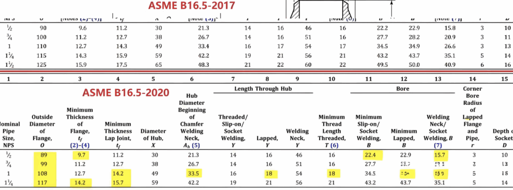
Comparison: ASME B16.5-2017 vs. ASME B16.5-2020
There are a few changes between ASME B16.5-2017 and ASME B16.5-2020, mainly to improve consistency between metric and imperial units
Find the summary changes of ASME B16.5 2020
1. Section 1.6 – Relevant Units
- 2017: U.S. Customary units were provided in Mandatory Appendix II.
- 2020: U.S. Customary tables have been relocated to the main text and redesignated with a “C” suffix (e.g., Table II-2-1.1 is now Table 2-1.1C). Additionally, U.S. Customary figures have been merged with SI figures. Former Mandatory Appendix II has been deleted, and the subsequent appendix redesignated accordingly.
2. Section 2.8 – Flange Types
- 2017: Did not include straight hub welding flanges.
- 2020: Introduced straight hub welding flanges in Classes 150 through 2500, expanding the range of flange options available for various applications.
3. Section 6.4 – Flange Facings
- 2017: Metric dimensions for flange sealing surface heights were 2 mm and 7 mm.
- 2020: Revised metric dimensions to align more precisely with their imperial counterparts, adjusting flange sealing surface heights from 2 mm and 7 mm to 1.5 mm and 6.4 mm, respectively.
4. Section 6.7 – Welding Neck Flanges Hub and Welding End Profiles
- 2017: Minimum flange thickness was designated as “C”.
- 2020: Changed the designation for minimum flange thickness from “C” to “tf”. Notably, this measurement no longer includes the 2.0 mm (0.06 in.) raised face for Classes 150 and 300 raised face flanges and flanged fittings, providing clearer guidance on flange dimensions.
5. Annex G – Flanged Fittings
- 2017: Flanged end fittings for Classes 400 and higher were listed with both SI and U.S. Customary units.
- 2020: Due to reduced demand, flanged end fittings conforming to ASME Class 400 and higher are now listed only with U.S. Customary units in Annex G, streamlining the standard’s content.
Note:the dimension changes in ASME B16.5 2020.
There are a few dimensional changes between ASME B16.5-2017 and ASME B16.5-2020,Below is an comparison example of the dimensions between ASME B16.5-2017 and ASME B16.5-2020,Highlighed in yellow.
So it is important to state the flange standard to be applied in the design and order sheet.