EN 10253-2 Butt Weld Fittings Specification | Carbon and Alloy Steel Fittings Manufacturer
EN 10253-2 covers the technical delivery requirements for seamless and welded butt weld fittings made of non-alloy and alloy steels for use in pressure piping and pressure vessels at room temperature, elevated, or low temperatures. These fittings are designed for butt welding to pipes and flanges according to relevant EN and ISO standards.
EN 10253-2 Butt weld fittings standard is one of the standards developed by the European Committee for Standardization (CEN). It specifies the dimensions, materials and other relevant requirements for seamless and welded steel pipes and fittings, especially for seamless and welded steel pipes and fittings used for pressure applications.
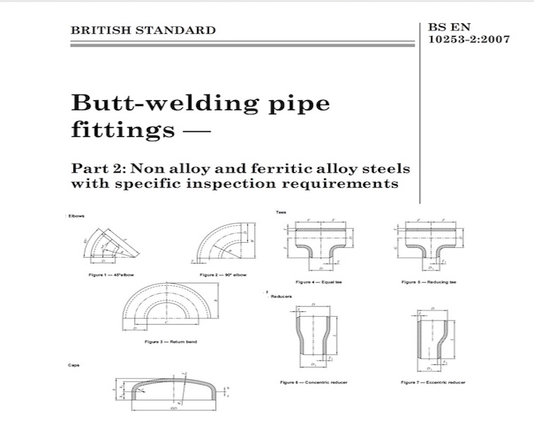
This Part of EN 10253 specifies the technical delivery requirements for seamless and welded butt-welding fittings (elbows, concentric and eccentric reducers, equal and reducing tees, caps) made of carbon and alloy steel which are intended for pressure purposes at room temperature, at low temperature or at elevated temperatures, and for the transmission and distribution of fluids and gases.
It specifies: type of fittings ;
type A : Butt-welding fittings with reduced pressure factor ;
type B : Butt-welding fittings for use at full service pressure ;
Fittings of type A
Type A fitting have the same wall thickness at the welding ends and at the body of the fitting than a pipe having the same specified wall thickness. Their resistance to internal pressure is less than that of a pipe with the same specified diameter, wall thickness and of the same steel grade. The determination of the reducing pressure factor is given in Annex A and tables of pressure factors are given in Annex B.
For reducers the wall thickness at the conical section shall be the specified wall thickness at the major end.
Fittings of type B
Fittings of type B have increased wall thickness at the body of the fitting. They will, in general, withstand the same pressure than a pipe having the same specified diameter, wall thickness and the same steel grade.
Wall thickness requirements for this type of fittings are defined by the calculation procedures given in Annex A. For some preferred, specified wall thicknesses the resulting wall thicknesses at the body of the fitting are listed in the tables given in Annex C.
EN 10253-2 Material introduction
EN 10253-2 is the standard specification for butt welding pipe fittings of non-alloy and ferritic alloy steels with specific inspection requirements. Typical materials include P235GH, P265GH, 16Mo3, 13CrMo4-5, P355NH, and L450QB, etc.
1. European Standard Pressure Vessel Steels
P235TR2, P265TR2, P235GH, and P265GH are all European-standard carbon structural steels, suitable for the manufacture of boilers and pressure vessels. Among them, the TR series is focused on boiler heating surface tubes, while the GH series is mostly used for pressure vessel shells. They have good weldability and medium-low temperature mechanical properties, ensuring the structural safety of pressure equipment.
P265GH in EN 10253-2: The yield strength is slightly higher than that of P235GH, about 265MPa, and the comprehensive mechanical properties are slightly better. It can be used in working conditions with slightly higher pressure and temperature, such as EN 10253-2 Butt Weld Fittings for gas pipelines with slightly higher pressure in some chemical plants.
2. Heat-Resistant Steels (for High-Temperature Working Conditions)
16Mo3, 10CrMo5-5, 13CrMo4-5, 10CrMo9-10, X11CrMo5, X11CrMo9-1, and X10CrMoVNb9-1 belong to Cr-Mo heat-resistant steels, which improve high-temperature strength and oxidation resistance through alloying elements such as Cr and Mo. They are widely used in superheater/reheater tubes of power plant boilers, chemical high-temperature reaction vessels, etc., and can work stably at 500~650℃ for a long time.
13CrMo4-5 in EN 10216-2: The addition of chromium (Cr) elements can improve the oxidation resistance and corrosion resistance of steel, and molybdenum (Mo) elements can improve the high temperature strength and creep resistance of steel. This material is often used in high temperature, high pressure and certain corrosion risk pipeline systems.
3. Low-Temperature Steels (Suitable for Deep-Cold Environments)
P355N/NH/NL1, P215NL, P265NL, 12Ni14, and X10Ni9 belong to low-temperature tough steels, which maintain good toughness at low temperatures of -20~-60℃ to avoid brittle fracture. Typical applications include liquefied natural gas (LNG) storage tanks, polar pipeline projects, low-temperature pressure vessels, etc., ensuring structural reliability in deep cold environments.
4. Pipeline Steels (Special for Oil and Gas Transmission)
L290NB, L360NB/QB, L415NB/QB, and L450QB belong to high-grade pipeline steels, used for long-distance oil and gas transmission pipelines. NB stands for the “normalized + normalized rolled” process, and QB stands for the “quenched + tempered” process. The strength grade increases from L290 to L450, with both corrosion resistance and impact resistance, meeting the requirements of pipeline projects with different pressures and terrains.
| Steel Name | Steel Number | C Content (%) | Si Content (%) | Mn Content (%) | P Max (%) | S Max (%) | Al Total (%) | Cr Content (%) | Cu Max (%) | Mo Content (%) | Nb Content (%) | Ni Content (%) | Ti Content (%) | V Content (%) | Other Requirements |
|---|---|---|---|---|---|---|---|---|---|---|---|---|---|---|---|
| P235TR2 | 1.0255 | 0.16 | 0.35 | 1.20 | 0.025 | 0.020 | ≥0.020 c | 0.30 b | 0.30 b | 0.08 b | 0.01 b | 0.30 b | 0.04 b | 0.02 b | Cr+Cu+Mo+Ni ≤0.70 |
| P265TR2 | 1.0259 | 0.20 | 0.40 | 1.40 | 0.025 | 0.020 | ≥0.020 c | 0.30 b | 0.30 b | 0.08 b | 0.01 b | 0.30 b | 0.04 b | 0.02 b | « |
| P235GH | 1.0345 | 0.16 | 0.35 | 1.20 | 0.025 | 0.020 | ≥0.020 c | 0.30 | 0.30 | 0.08 | 0.01 b | 0.30 | 0.04 b | 0.02 b | « |
| P265GH | 1.0425 | 0.20 | 0.40 | 1.40 | 0.025 | 0.020 | ≥0.020 c | 0.30 | 0.30 | 0.08 | 0.01 b | 0.30 | 0.04 b | 0.02 b | « |
| 16Mo3 | 1.5415 | 0.12-0.20 d | 0.35 | 0.40-0.90 | 0.025 | 0.020 | ≤0.040 | 0.30 | 0.30 | 0.25-0.35 | – | 0.30 | – | – | – |
| 10CrMo5-5 | 1.7338 | 0.15 | 0.50-1.00 | 0.30-0.60 | 0.025 | 0.020 | ≤0.040 | 1.00-1.50 | 0.30 | 0.45-0.65 | – | 0.30 | – | – | – |
| 13CrMo4-5 | 1.7335 | 0.10-0.17 d | 0.35 | 0.40-0.70 | 0.025 | 0.020 | ≤0.040 | 0.70-1.15 | 0.30 | 0.40-0.60 | – | 0.30 | – | – | – |
| 10CrMo9-10 | 1.7380 | 0.08-0.14 | 0.50 | 0.30-0.70 | 0.025 | 0.020 | ≤0.040 | 2.00-2.50 | 0.30 | 0.90-1.10 | – | 0.30 | – | – | – |
| X11CrMo5 | 1.7362 | 0.08-0.15 | 0.15-0.50 | 0.30-0.60 | 0.025 | 0.020 | ≤0.040 | 4.00-6.00 | 0.30 | 0.45-0.65 | – | – | – | – | – |
| X11CrMo9-1 | 1.7386 | 0.08-0.15 | 0.25-1.00 | 0.30-0.60 | 0.025 | 0.020 | ≤0.040 | 8.00-10.00 | 0.30 | 0.90-1.10 | – | – | – | – | – |
| X10CrMoVNb9-1 | 1.4903 | 0.08-0.12 | 0.20-0.50 | 0.30-0.60 | 0.020 | 0.010 | ≤0.040 | 8.00-9.50 | 0.30 | 0.85-1.05 | 0.06-0.10 | 0.40 | – | 0.18-0.25 | N: 0.030-0.070 |
| P355N | 1.0562 | 0.20 | 0.50 | 0.90-1.70 | 0.025 | 0.020 | ≥0.020 c | 0.30 b | 0.30 e | 0.08 e | 0.05 | 0.50 | 0.04 | 0.10 | N ≤0.02; Nb+Ti+V ≤0.12 |
| P355NH | 1.0565 | 0.20 | 0.50 | 0.90-1.70 | 0.025 | 0.020 | ≥0.020 c | 0.30 b | 0.30 e | 0.08 e | 0.05 | 0.50 | 0.04 | 0.10 | N ≤0.02; Nb+Ti+V ≤0.12 |
| P355NL1 | 1.0566 | 0.18 | 0.50 | 0.90-1.70 | 0.025 | 0.020 | ≥0.020 c | 0.30 b | 0.30 e | 0.08 e | 0.05 | 0.50 | 0.04 | 0.10 | N ≤0.02; Nb+Ti+V ≤0.12 |
| P215NL | 1.0451 | 0.15 | 0.35 | 0.40-1.20 | 0.025 | 0.020 | ≥0.020 c | 0.30 | 0.30 | 0.08 | 0.10 | 0.30 | 0.04 | 0.02 | – |
| P265NL | 1.0453 | 0.20 | 0.40 | 0.60-1.40 | 0.025 | 0.020 | ≥0.020 c | 0.30 | 0.30 | 0.08 | 0.10 | 0.30 | 0.04 | 0.02 | – |
| 12Ni14 | 1.5637 | 0.15 | 0.15-0.35 | 0.30-0.80 | 0.025 | 0.010 | – | – | 0.30 | – | – | 3.25-3.75 | – | 0.05 | – |
| X10Ni9 | 1.5682 | 0.13 | 0.15-0.35 | 0.30-0.80 | 0.020 | 0.010 | – | – | 0.30 | 0.10 | – | 8.50-9.50 | – | 0.05 | N ≤0.012 |
| L290NB | 1.0484 | 0.17 | 0.40 | 1.20 | 0.025 | 0.020 | 0.015-0.060 | 0.30 | 0.25 | 0.10 f | 0.05 | 0.30 | 0.04 | 0.05 | CEV ≤0.42; N ≤0.012 |
| L360NB | 1.0582 | 0.20 | 0.45 | 1.60 | 0.025 | 0.020 | 0.015-0.060 | 0.30 | 0.25 | 0.10 f | 0.05 | 0.30 | 0.04 | 0.15 | CEV ≤0.45; N ≤0.012; V+Nb+Ti ≤0.15 |
| L360QB | 1.8948 | 0.16 | 0.45 | 1.40 | 0.025 | 0.020 | 0.015-0.060 | 0.30 | 0.25 | 0.10 f | 0.05 | 0.30 | 0.04 | 0.05 | CEV ≤0.42; N ≤0.012 |
| L415NB | 1.8972 | 0.21 | 0.45 | 1.60 | 0.025 | 0.020 | 0.015-0.060 | 0.30 | 0.25 | 0.10 f | 0.05 | 0.30 | 0.04 | 0.15 | CEV ≤0.42; N ≤0.012; V+Nb+Ti ≤0.15 |
| L415QB | 1.8947 | 0.16 | 0.45 | 1.60 | 0.025 | 0.020 | 0.015-0.060 | 0.30 | 0.25 | 0.10 f | 0.05 | 0.30 | 0.04 | 0.08 | CEV ≤0.43; N ≤0.012; V+Nb+Ti ≤0.15 |
| L450QB | 1.8952 | 0.16 | 0.45 | 1.60 | 0.025 | 0.020 | 0.015-0.060 | 0.30 | 0.25 | 0.10 f | 0.05 | 0.30 | 0.06 | 0.09 | CEV ≤0.45; N ≤0.012; V+Nb+Ti ≤0.15 |
Mechanical Property of EN 10253-2 Butt Weld Fittings
| Mechanical properties | ||||||||||
| Steel grade | Upper yield strength or proof strength ReH or Rp0,2 min. for wall thicknesses T in mm N/mm2 | Tensile strength Rm for wall thicknesses T in mm N/mm2 | Elongation A min. % | |||||||
| Name | Number | T ≤ 16 | 16 < T ≤ 40 | 40 < T ≤ 60 | 60 < T ≤ 100 | T ≤ 16 | 16 < T ≤ 60 | 60 < T ≤ 100 | Longitudinal | Transverse |
| P235TR2 | 1.0255 | 235 | 225 | 215 | – | 360-500 | 360-500 | – | 25 | 23 |
| P265TR2 | 1.0259 | 265 | 255 | 245 | – | 410-570 | 410-570 | – | 21 | 19 |
| P235GH | 1.0345 | 235 | 225 | 215 | – | 360-500 | 360-500 | – | 25 | 23 |
| P265GH | 1.0425 | 265 | 255 | 245 | – | 410-570 | 410-570 | – | 23 | 21 |
| 16Mo3 | 1.5415 | 280 | 270 | 260 | – | 450-600 | 450-600 | – | 22 | 20 |
| 10CrMo5-5 | 1.7338 | 275 | 275 | 265 | – | 410-560 | 410-560 | – | 22 | 20 |
| 13CrMo4-5 | 1.7335 | 290 | 290 | 280 | – | 440-590 | 440-590 | – | 22 | 20 |
EN 10253-2 Butt Weld Fittings Dimension Tolerance
Tolerances for ovality are following:
At the welding ends:
D ≤ 273,0 Included in the diameter tolerance ;
273,0 < D ≤ 610 2 % ;
D > 610 1 % ;
On the body for elbows and return bends : 4 %.
The ovality shall be calculated as follows :
Ov = 100 (Dmax -Dmin) / D in %
Where:
Dmax is the bigger diameter in one section, expressed in millimetres ;
Dmin is the smaller diameter in the same section, expressed in millimetres ;
D is the specified diameter, expressed in millimetres.
Wall thickness tolerances are indicated in Table 1. For fittings type B, the minus tolerances on T apply also for the other values of the wall thickness as defined in Annex A.
| Table 1 — Wall thickness tolerances at the welding ends | |||
| D mm | T mm | Wall thickness tolerance | |
| Minus | Plus | ||
| ≤ 610 | ≤ 4 > 4 | – 12,5 % | + 20 % |
| > 610 | Seamless | – 12,5 % | + 20 % |
| Welded ≤ 10 > 10 | – 0,35 mm – 0,5 mm | + 20 % | |
For the dimensions specific to fittings, the tolerances are given in Table 2
| Table 2 — Tolerances on specific dimensions and form | |||||
| Dimensions in millimetres | |||||
| D | F-G-L-W | B-Z | C | h | P |
| ≤ 114,3 | ± 2 | ± 7 | ± 7 | ± 4 | 2 |
| 114,3 < D ≤ 219,1 | ± 2 | ± 7 | ± 7 | ± 7 | 4 |
| 219,1 < D ≤ 406,4 | ± 3 | ± 7 | ± 10 | ± 7 | 6 |
| 406,4 < D ≤ 762 | ± 3 | ± 10 | ± 10 | ± 7 | 7 |
| 762 < D | ± 5 | ± 12 | ± 10 | ± 10 | 9 |
Designation of fittings
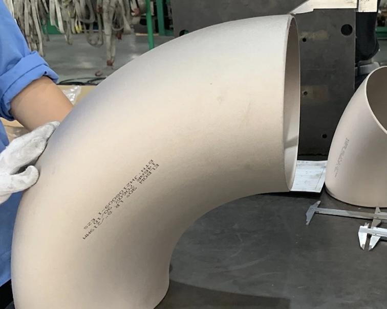
EN 10253-2 Elbows
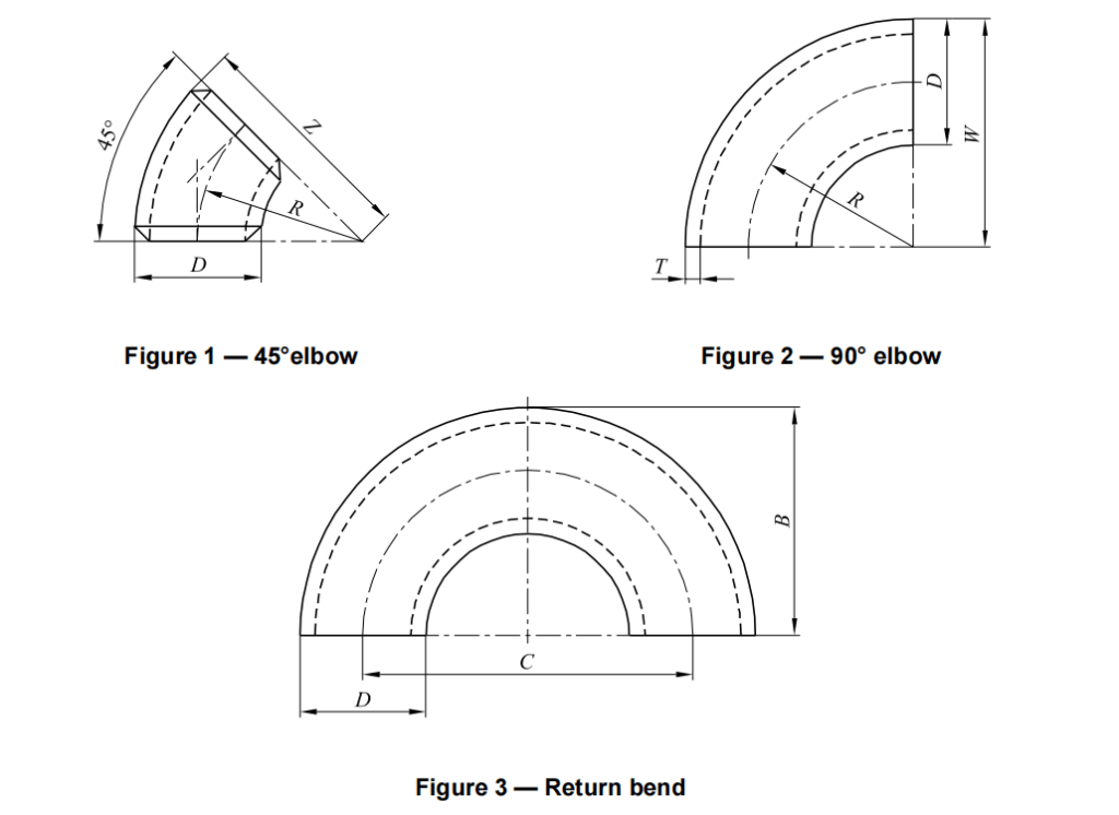
EN 10253-2 Elbows and return bends are designated by the model (2D, 3D or 5D), the angle, the outside diameter D.
Download Dimensions of butt welding elbows 2D 3D 5D EN 10253-2
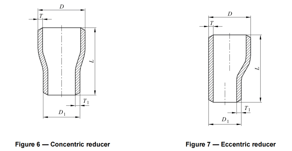
EN 10253-2 Reducer
Reducers are designated by the model (concentric or eccentric), the major diameter D, the minor diameter D 1.
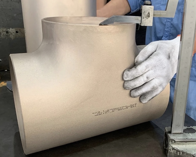
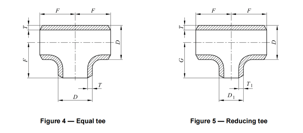
EN 10253-2 Tee
Equal tees are designated by the outside diameter D.
Reducing tees are designated by the major diameter D, the minor diameter D 1.
Download Dimensions of EN10253 butt welding Tee
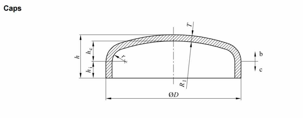
Caps are designated by the outside diameter D.
EN 10253-2 Butt Weld Caps
EN 10253-2 caps are mainly used to close or terminate a pipeline, preventing fluid leakage or contamination. They are commonly applied in high-pressure pipelines, boilers, and process equipment
Download Dimension of EN 10253-2 caps
Examples of an order
6.3.1 Example 1
1000 elbows in accordance with this European Standard, of type A (not having an increased wall thickness for the body of the fitting) and model 3D, with angle 90°, having an outside diameter 114, and a wall thickness 6,3, made of steel grade P265GH.
1000 elbows – EN 10253-2 – Type A – Model 3D – 90°- 114,3 X 6,3 – P265GH
6.3.2 Example 2
500 reducing tees in accordance with this European Standard of type B (having an increased wall thickness for the body of the fitting), with dimensions 114,3 X 6,3 – 88,9 X 4,0 and made of steel grade P265GH.
500 reducing tees – EN 10253-2 – Type B – 114, 3X6,3 – 88,9 X 4,0 – P265GH
Applications
- Power Generation (Boilers, HRSG)
- Oil & Gas and Refinery Pipelines
- Chemical and Petrochemical Plants
- Pressure Vessel Fabrication
- Steam and Heat-Exchanger Systems
Related Products
- EN 10222-2 Forged Flanges
- EN 10216-2 Seamless Steel Pipes
- EN 1092-1 Flanges
- EN 10253-4 Butt Weld Fittings
- ASME B16.9 Butt Weld Fittings